Corrosion reducing minimum contact clamp for supporting and securing tubing

a technology of corrosion reduction and clamping, which is applied in the direction of pipe supports, mechanical devices, pipe/joints/fittings, etc., can solve the problems of disadvantageous economic and efficient implementation of such clamps and the moisture holding of insulation materials, and achieve the effect of reducing electrolysis and corrosion of tubing

Inactive Publication Date: 2018-01-09
LEMAN CHRISTOPHER
View PDF32 Cites 2 Cited by
  • Summary
  • Abstract
  • Description
  • Claims
  • Application Information

AI Technical Summary

Benefits of technology

[0004]It is an object of the present invention to provide a clamp or an arrangement of clamps in a clamping system that provides minimum contact between the tubing support surfaces of the clamp and the tubing to allow for ventilation which minimizes electrolysis and corrosion of the tubing while offering a compact clamping system permitting uniform configurations of a variety of tubes with equal or different diameters.
[0006]Embodiments of the present invention provide a corrosion reducing minimum contact clamp comprised of cylindrically shaped bodies made from a metallic, composite or plastic material for forming upper and lower clamp support bodies for securing an individual row of tubes or a rectangular array of tubes, including one or more spaced-apart tubing accommodating grooves of a shape having spaced groove inner and outer edges that form conical frustums. The grooves can be of equal or unequal size within the same clamp support bodies in order to enable tubes of different sizes or multiple tubes of the same size to be accommodated and properly seated side by side within the same tubing clamp.

Problems solved by technology

However, the greater the contact area between the clamping supports and the tubing, the more the contact area is likely to collect and hold moisture.
However, such additional insulating materials hold moisture.
Accordingly, such configurations are disadvantageous with respect to the economical and efficient implementation of such clamps in clamping systems for supporting tubing of various types of materials and sizes typically found in industrial installations and that exist in potentially corrosive environments.

Method used


Image

  • Corrosion reducing minimum contact clamp for supporting and securing tubing
  • Corrosion reducing minimum contact clamp for supporting and securing tubing
  • Corrosion reducing minimum contact clamp for supporting and securing tubing

Examples


Embodiment Construction

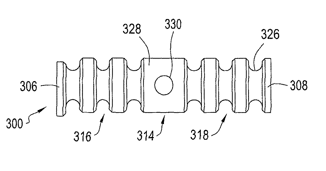
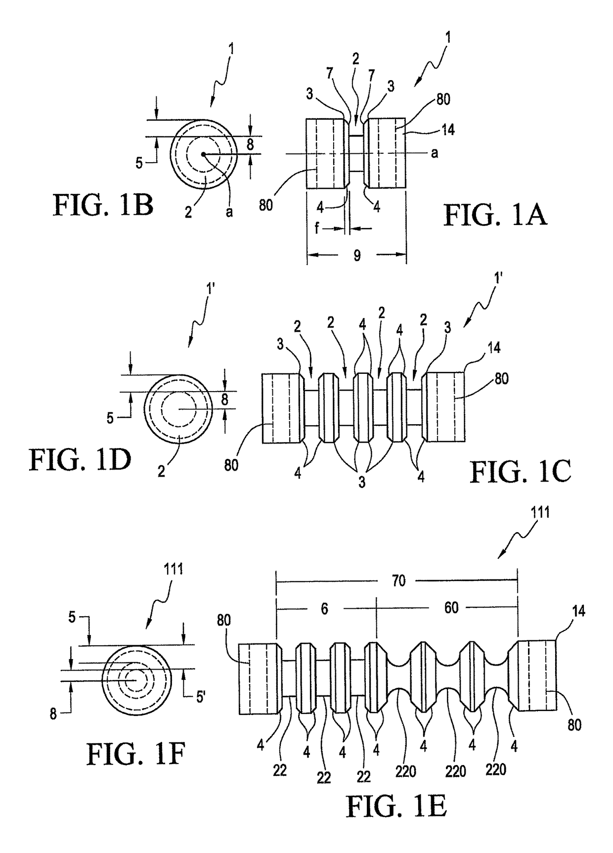
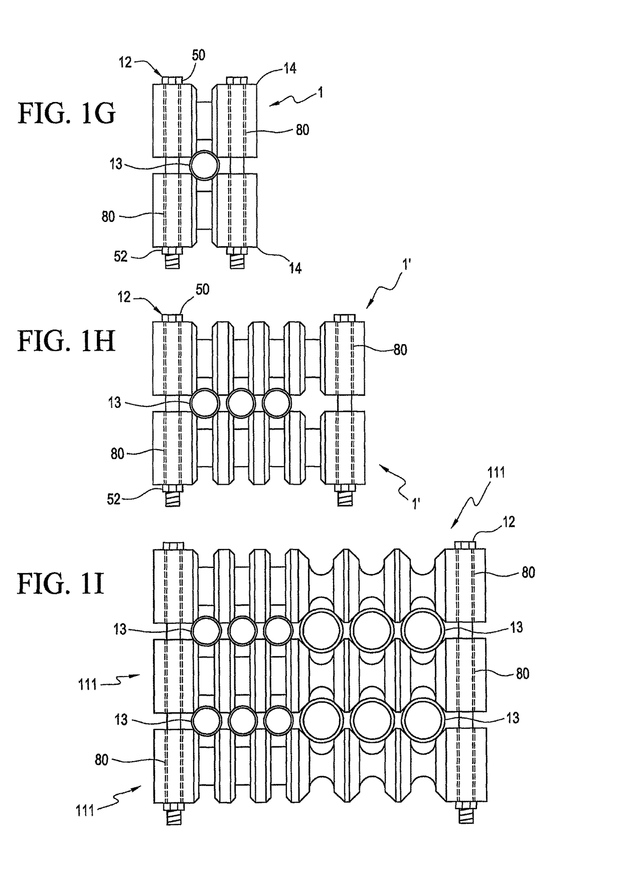
[0043]FIG. 1A shows a first preferred embodiment of a clamp support body of right circular cylindrical shape, generally at 1, and having a single circular groove 2 with features of a wedge and having groove outer edges 3 and groove inner edges 7 which are spaced apart from each other at a radial outer portion of the groove. Each pair of spaced outer and inner groove edges 3; 7 cooperate to form one of two mirrored right conical frustums 4, each such conical frustum 4 having a frustum width “f”. The right conical frustums 4 each formed by the groove edges 3; 7 on one of the two sides of the groove 2 each form a wedge and are the contact surfaces for tubing, when clamped. The wedge shape prevents the tubing from shifting to either side. The conical frustums 4, each formed by one pair of the groove edges 3; 7, are each a truncated conical surface that comes in contact with the tubing, which is typically of circular shape, resulting in a minimal contact area of the clamp and tubing. A g...


PUM


Abstract

Tubing clamps having a minimum contact area between the tubes and supporting surfaces of clamp support bodies are provided for minimizing the collection and retention of liquids at the supporting surfaces. A minimum spacing is maintained between the tubes supported by the tubing clamps while maintaining sufficient ventilation between the tubes and the clamp support bodies to permit drying of any liquids which contact the tubes and the clamp support bodies at tubing support points. This prevents electrolysis and corrosion which may be caused by liquid retention and by contact between dissimilar metals. The tubing clamps are adapted to secure tubes having differing outer diameters in a single row or in multiple rows, such as in a stacked configuration. The clamps are provided with upper and lower supports, each having matching grooves that have chamfered edges forming the upper and lower tubing contact surfaces. The supports are secured together with fasteners to clamp the tubing therebetween.

Description

CROSS REFERENCE TO RELATED APPLICATION[0001]This application is a continuation-in-part of prior U.S. patent application Ser. No. 14 / 261,928, filed Apr. 25, 2014, the disclosure of which is expressly incorporated herein in its entirety by reference.FIELD OF THE INVENTION[0002]The present invention relates to the clamping and supporting of tubing used to transport fluids, chemicals, oils and gases in industries, such as oil and gas drilling; and production and refining, where such tubing is commonly used. Other industries using tubing include shipping, military installations and equipment, food production installations, manufacturing sites, etc. In addition, the present invention is utilizable in corrosive environments, such as marine environments, where minimum contact between tubing, and the clamps that support the tubing, is preferable in order to reduce the accumulation of moisture contacting the tubing at the support area, which contact creates a risk of pitting and corrosion of ...

Claims


Application Information

Patent Timeline
Patent Type & Authority Patents(United States)
IPC IPC(8): F16L3/223F16L3/10
CPCF16L3/2235F16L3/223F16L3/10F16L3/1091
Inventor ROBERT, JR., ATMAR KEITH
Owner LEMAN CHRISTOPHER
Why Eureka
Try Eureka