Spacer nut manufacturing method

a manufacturing method and spacer technology, applied in the direction of threaded fasteners, bolts, other domestic articles, etc., can solve the problems of large introduction cost, inability to form a roll shape, and generally rather expensive nc lathes, so as to reduce the number of times that the material is replenished, reduce the cost of material supply, and high production efficiency

Inactive Publication Date: 2012-09-11
WATOKU
View PDF2 Cites 2 Cited by
  • Summary
  • Abstract
  • Description
  • Claims
  • Application Information

AI Technical Summary

Benefits of technology

[0031]Further, the press working of the first through fifth steps is conducted through die frame shaping, so that, in addition to the effect of the invention, it is possible to make the configuration of the products uniform, to achieve an improvement in terms of product quality, and to achieve a further improvement in terms of production efficiency.
, it is possible to make the configuration of the products uniform, to achieve an improvement in terms of product quality, and to achieve a further improvement in terms of production efficiency.

Problems solved by technology

However, an NC lathe is generally rather expensive, and has a problem in that it involves a very large introduction cost when it is newly introduced as equipment.
Further, since the material is a cylindrical bar material, it cannot be formed into a roll shape as in the case of a metal plate material.
Thus, due to restrictions in terms of handling, there is used a material previously cut in a length dimension of approximately 1 to 2 meters.
Thus, in the machining operation, it is necessary to newly replenish a bar material as appropriate, resulting in a rather poor production efficiency; further, since it is necessary to previously machine the material into a cylindrical shape, the material supply cost involved is rather high.
Despite the above-mentioned problems, there has been proposed until now no effective manufacturing method to take the place of the manufacturing method using an NC lathe.

Method used


Image

  • Spacer nut manufacturing method
  • Spacer nut manufacturing method
  • Spacer nut manufacturing method

Examples


Embodiment Construction

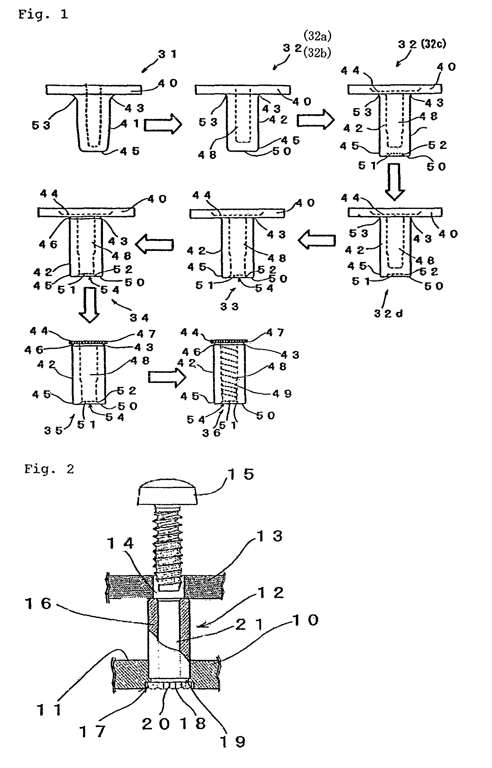
[0074]A mode for carrying out the present invention will be described with reference to the drawings.

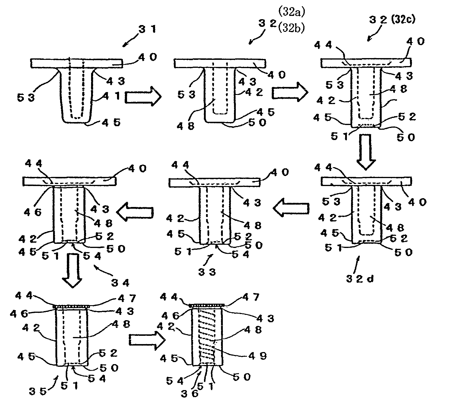
[0075]As shown in FIG. 1, a spacer nut manufacturing method 30 according to the present invention comprises: a first step 31 of forming a protrusion 41 of a predetermined length by press working on a metal plate material 40 having a predetermined thickness dimension; a second step 32 of forging the protrusion 41 into a shaft portion 42 in the form of a bottomed cylinder and forming a flange portion 44 at the peripheral edge of a proximal end portion 43 of the shaft portion 42 by press working; a third step 33 of forming an opening 54 at a distal end portion 45 of the shaft portion 42 by press working; a fourth step 34 of pressing the proximal end portion 43 of the shaft portion 42 radially inwards to form a groove portion 46 extending in the circumferential direction of the shaft portion 42 by press working; a fifth step 35 of stamping the flange portion 44 from the metal plate mater...


PUM


Abstract

A spacer nut manufacturing method which does not use a NC lathe and which allows machining using existing press working equipment, involves a low parts supply cost, and which helps to achieve a high production efficiency at a low production cost is disclosed. The method of manufacturing a spacer nut arranged between a casing and a board arranged inside the casing and serving to fix the board in position while keeping the board spaced apart from the casing by a predetermined distance dimension is presented.

Description

TECHNICAL FIELD[0001]The present invention relates to a method of manufacturing a spacer nut which is arranged between a casing and a board of a computer or the like in order to fix the casing and the board in position while keeping them spaced apart from each other by a predetermined distance dimension when mounting the board in the casing.BACKGROUND ART[0002]When fixing a board in position within the casing of a personal computer or the like, it is necessary for the board to be spaced apart from the inner side surface of the casing by a predetermined dimension in order to prevent confinement of heat, a shock from the outside, etc. Thus, as shown in FIG. 2, a spacer nut 12 formed in a substantially cylindrical configuration is forced into an inner side surface 11 of a casing 10 and fixed in position so as to be erect, and a screw passing hole portion 14 previously provided in a board 13 and the spacer nut 12 are matched with each other; then, the board 13 is placed on the spacer nu...

Claims


Application Information

Patent Timeline
Patent Type & Authority Patents(United States)
IPC IPC(8): B21D53/24B21H3/08B21K1/64
CPCB21K1/14B21K1/66B21D53/24B21K23/00B21K21/08F16B37/145
Inventor KADONO, YASUYUKIKADONO, YUJI
Owner WATOKU
Why Eureka
Try Eureka