Corrosion reducing minimum contact clamp for supporting and securing tubing

Active Publication Date: 2014-10-30
LEMAN CHRISTOPHER
View PDF21 Cites 5 Cited by
  • Summary
  • Abstract
  • Description
  • Claims
  • Application Information

AI Technical Summary

Benefits of technology

[0003]It is an object of the present invention to provide a clamp or an arrangement of clamps in a clamping system that provides minimum contact between the tubing support surfaces and the tubing to allow for ventilation that minimizes electrolysis and corrosion of the tubing while offering a compact clamping system permitting uniform configurations of a variety of tubes with equal or different diameters.
[0004]The clamping supports enable a number of tubes to be secured and supported within the same clamping system using one or more grooves of equal or unequal size (when supporting multiple tubes of the same OD) formed in the clamp support bodies in order to enable the tubes to seat properly with tubing engaging

Problems solved by technology

However, the greater the contact area between the clamping supports and the tubing, the more the contact area is likely to collect and hold moisture.
However, such additional insulating materials hold moisture.
Accordingly, such designs are disadva

Method used


Image

  • Corrosion reducing minimum contact clamp for supporting and securing tubing
  • Corrosion reducing minimum contact clamp for supporting and securing tubing
  • Corrosion reducing minimum contact clamp for supporting and securing tubing

Examples


Embodiment Construction

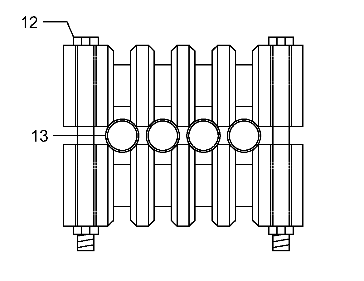
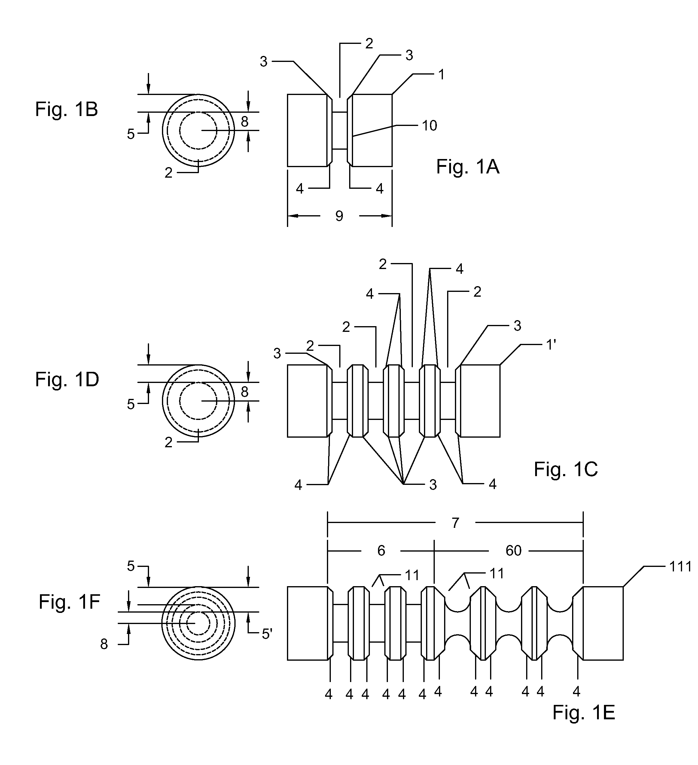
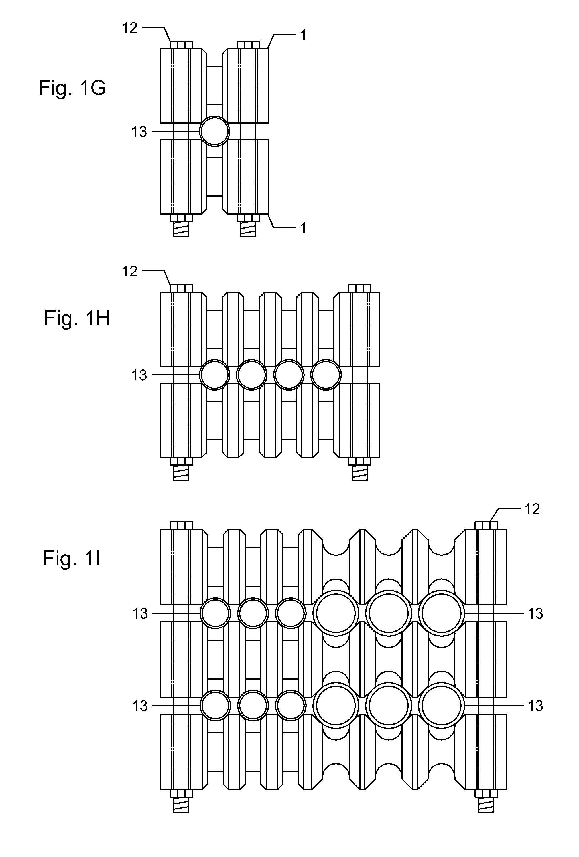
[0023]In FIG. 1, FIG. 1 A shows a clamp support body of right circular cylindrical shape 1 having a single circular groove 2 with features of a wedge and quadrilateral shape and having chamfered edges 3 forming two mirrored right conical frustums 4. The chamfered edges 3 form a wedge and are the contact points for tubing when clamped. The wedge shape prevents the tubing from shifting to either side. The conical frustums 4 formed by the chamfered edge 3 is a circular object that comes in contact with the tubing which is also of circular shape resulting in a minimal contact area of the clamp and tubing. Groove depth 5 provides a space between the surface of the clamp and the tubing. This space is required to allow ventilation for drying any liquids that might be present or accumulate as a result of the installation environment. In one embodiment of the present invention, the distance from the axis of symmetry 8 to the depth of the groove 5 as shown in FIG. 1B is not less than 0.125 in...


PUM


Abstract

Tubing clamps having a minimum contact area between the tubes and the clamps supporting surfaces are provided for minimizing the collection and retaining of liquids at the supporting surfaces. A predetermined minimum spacing is maintained between the tubes supported by the tubing clamps while maintaining sufficient ventilation between the tubes and the clamps to permit drying of any liquids which contact the tubes and the clamps at the support points. This prevents electrolysis and corrosion caused by liquid retention and contact of dissimilar metals. Further, the tubing clamps are readily adapted to secure tubes of different outer diameters in a single row or multiple rows, such as in a stacked configuration. The clamps are provided with upper and lower supports, each having matching grooves that have chamfered edges forming the upper and lower tubing contact surfaces. The supports are secured together with fasteners to clamp the tubing therebetween.

Description

FIELD OF THE INVENTION[0001]The invention relates to the clamping and supporting of tubing used to transport fluids, chemicals, oils and gases in industries, such as oil and gas drilling; and production and refining, where tubing is commonly used. Other industries using tubing include shipping, military installations and equipment, food production installations, manufacturing sites, etc. In addition the invention is applicable in corrosive environments, such as marine environments, where minimum contact between tubing and the clamps that support the tubing is preferable in order to reduce the accumulation of moisture contacting the tubing at the support area which creates a risk of pitting and corrosion of the tubing.DESCRIPTION OF RELATED ART[0002]Clamping systems of the prior art include solutions for solving or reducing the problems associated with electrolysis and corrosion of tubing. However, the greater the contact area between the clamping supports and the tubing, the more th...

Claims


Application Information

Patent Timeline
IPC IPC(8): F16L3/10
CPCF16L3/1091F16L3/2235F16L3/223
Inventor ROBERT, JR., ATMAR KEITH
Owner LEMAN CHRISTOPHER
Why Eureka
Try Eureka