Fuel cell system and shutdown method for a fuel cell system

Inactive Publication Date: 2006-03-09
BDF IP HLDG
View PDF5 Cites 11 Cited by
  • Summary
  • Abstract
  • Description
  • Claims
  • Application Information

AI Technical Summary

Benefits of technology

[0020] It is the objective of the invention to present a fuel cell sy

Problems solved by technology

Even a purge with air of the anode area or the anode loop c

Method used


Image

  • Fuel cell system and shutdown method for a fuel cell system
  • Fuel cell system and shutdown method for a fuel cell system
  • Fuel cell system and shutdown method for a fuel cell system

Examples


Example

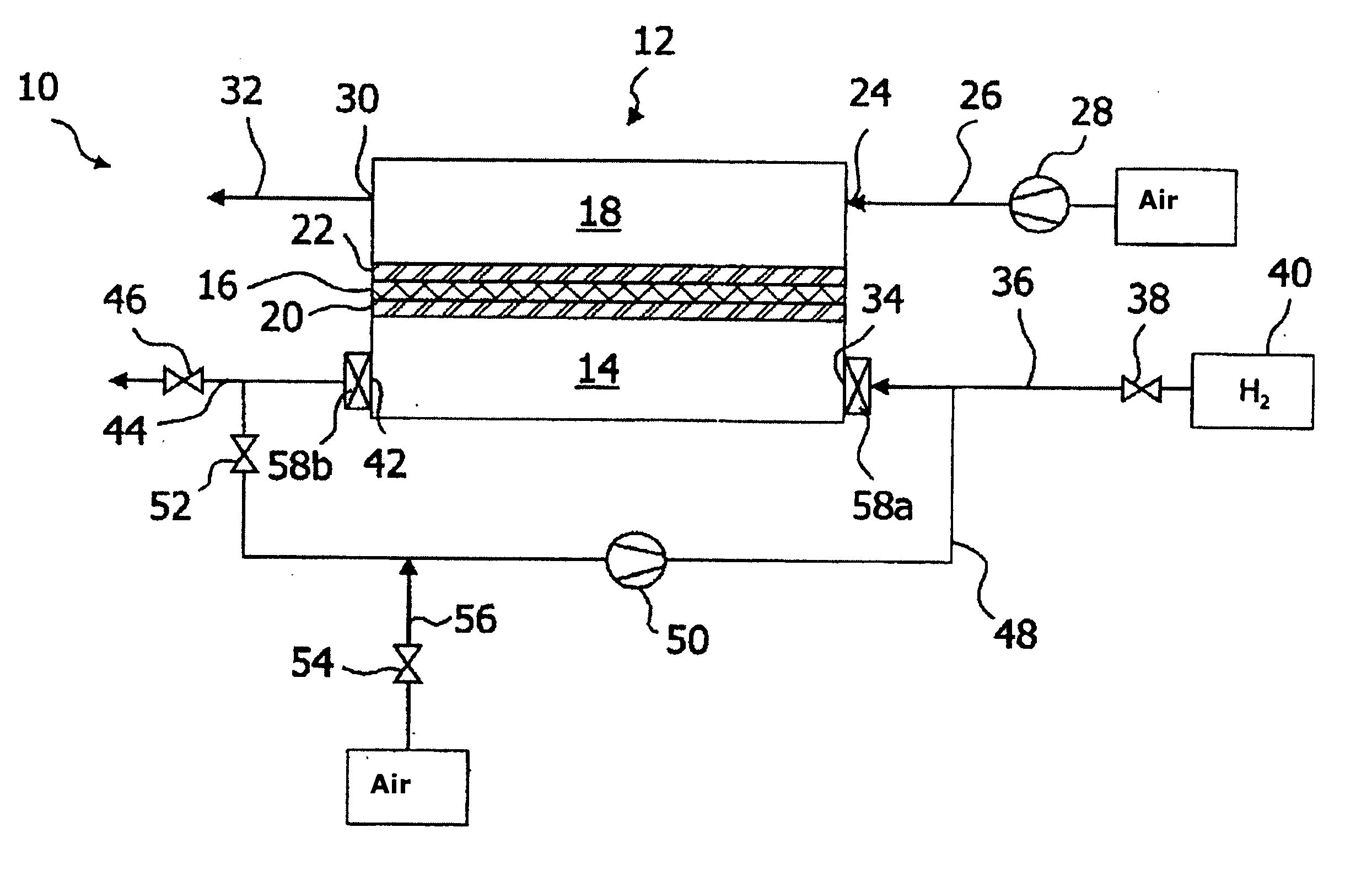
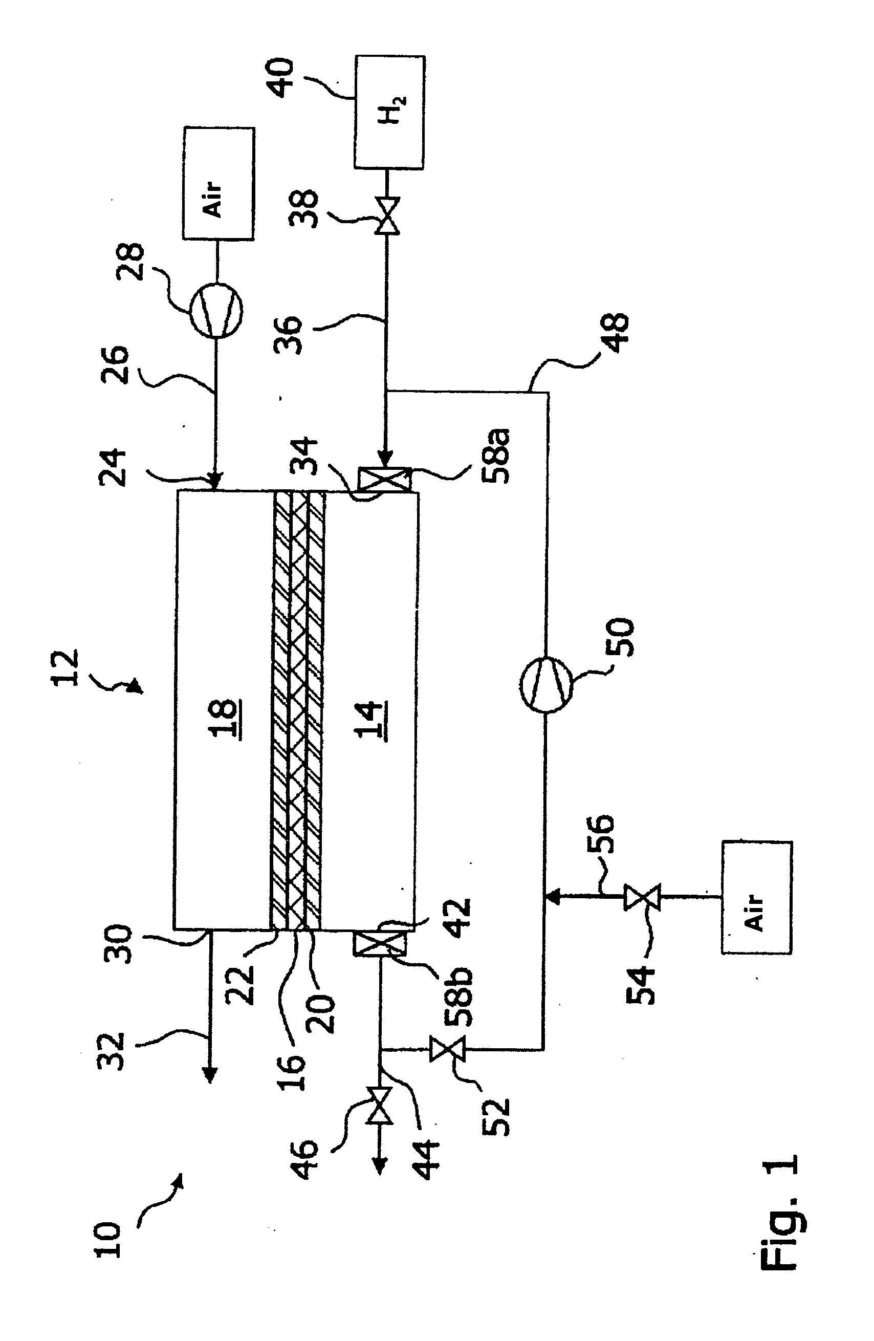
[0040]FIG. 1 shows a fuel cell system, labelled 10 in its entirety, comprising one fuel cell 12, which contains one anode area 14, as well as one cathode area 18 that is separated from the anode area 14 by an electrolyte 16. The electrolyte 16 is developed in the form of a proton-conducting polymer film. The anode area 14 and the cathode area 18 each contain a catalyst 20, 22, which have been applied onto a carbon carrier (not shown in detail), for the catalytic conversion of reactants supplied to the fuel cell 12. Even though only a single fuel cell 12 is shown in FIG. 1, the fuel cell system 10 comprises a larger number of fuel cells 12, which are stacked on top of each other to form a so-called fuel cell stack.

[0041] The inlet 24 of the cathode area 18 is connected to the ambient air via a cathode gas supply line 26, which contains a pump 28. An outlet 30 of the cathode area 18 opens into a cathode gas discharge line 32.

[0042] An inlet 34 of the anode area 14 is connected to a ...


PUM


Abstract

A fuel cell system having at least one fuel cell, which possesses one anode area as well as one cathode area that is separated from the anode area by an electrolyte. The anode area and the cathode area each contain one catalyst for the catalytic conversion of reactants being supplied to the fuel cell. During downtime periods of the fuel cell, the anode area is filled with air or oxygen. Provided in the area of an inlet and/or in the area of an outlet of the anode area is an additional catalyst for the catalytic conversion of hydrogen with oxygen, which is set up to catalytically convert hydrogen diffusing towards the anode area during downtime periods of the fuel cell when the anode area is filled with air or oxygen.

Description

CROSS-REFERENCES TO RELATED APPLICATIONS [0001] This application claims the benefit under 35 U.S.C. § 119(e) of U.S. Provisional Patent Application No. 60 / 654,393 filed Feb. 18, 2005, and also claims priority to German Application No. 10 2004 042 806.9 filed Sep. 3, 2004; both of these applications are incorporated herein by reference in their entireties.BACKGROUND OF THE INVENTION [0002] 1. Field of the Invention [0003] The invention generally pertains to a fuel cell system as well as to a method to shut down a fuel cell system. [0004] 2. Description of the Related Art [0005] Typical fuel cells in use today comprise one cathode area as well as one anode area, which is separated from the cathode area by an electrolyte. Different electrolytes are used for different types of fuel cells. For example, the electrolyte of a polymer-electrolyte-membrane fuel cell is a proton-conducting membrane. During operation of the fuel cell, the anode side is supplied with hydrogen while the cathode s...

Claims


Application Information

Patent Timeline
IPC IPC(8): H01M8/00H01M8/04
CPCH01M4/92H01M8/04097H01M8/04223Y02E60/50H01M2004/8684H01M2008/1095H01M8/04231H01M8/04228H01M8/04303
Inventor LIMBECK, UWE M.RICHTER, HOLGER
Owner BDF IP HLDG
Why Eureka
Try Eureka