Protective covers

a protective cover and cover technology, applied in the field of protective covers, can solve the problems of creating a microclimate, affecting freezing in place, etc., and achieve the effects of preventing humidity buildup, preventing or at least minimizing oxidation and corrosion of the covered object, and ensuring the appearance of the cover

Active Publication Date: 2015-12-01
L&C PROTEC INC
View PDF11 Cites 5 Cited by
  • Summary
  • Abstract
  • Description
  • Claims
  • Application Information

AI Technical Summary

Benefits of technology

[0015]In accordance with an exemplary embodiment of this invention, the present invention includes a hydrophobic but air-permeable middle layer which prevents build-up of a microclimate and stabilizes the pressure under the cover, while still providing the desired water resistance performance needed. An air permeable protective cover is provided that is designed to prevent the ingress of moisture but, at the same time, to allow moisture vapor underneath the cover to readily pass through to the outer environment, thereby preventing humidity buildup and thus helping to prevent or at least minimize oxidation and corrosion of the covered object caused by condensation of any moisture trapped in the air under the cover.
[0016]In the underlying technology, the cover is composed of several laminated layers of different materials. The multiple layers include at least an outer textile layer, an intermediate film or membrane of ePTFE or other similar hydrophobic material having good air permeability and moisture-vapor-transmission properties, and an inner textile layer that faces toward the object being covered. For specific applications, the ePTFE membrane may be an air permeable, breathable, treated membrane such as an eVENT® membrane available from BHA Technologies. An optional fourth fabric layer between the outer layer and the film or membrane may incorporate Super Absorbing Polymers (SAPs) to prevent reabsorption of moisture back through the cover.
[0019]In all cases, the inner textile layer may have material such as silicone dots applied to the inner face thereof, so that contact between the cover and the object to be protected is minimized if not eliminated, and to thereby enhance the moisture vapor transmission away from the object.
[0024]In the preferred embodiment of the present invention, the protective cover features an additional protection. The enhancement provides new levels of durability (resistance to abrasion and wear) as well as new levels of resistance to environmental conditions including exposure to solar radiation, temperature and humidity. The invention involves treatments to fibers, yarns and / or fabrics that provide a higher surface wear, and greatly improved durability to sunlight exposures.
[0025]In a first embodiment, a top coating of ceramic based material, a curable coating including metal or metal oxide pigments, fire resistant components and / or UV absorbing components is applied to the outermost layer. In another embodiment, the threads of the outer layer fabric may be individually treated with such a protective coating, while in yet another embodiment, if the threads of the fabric are extruded, a co-extruded protective coating may be applied directly to the threads. In yet another embodiment, carbon nanotube fibers may be utilized as or incorporated into (along with other fibers or threads) the outer layer. Each additional protection layer is designed to increase the durability of the cover material and protect the cover material from damage caused by wind, sand, and other debris as well as protect from solar degradation caused by UV light.
[0026]In another embodiment, a permanent, highly breathable and highly durable electro-static discharge feature is added by laying down a carbon based printed pattern on the inside of the laminate, providing a discharge rate of 0.5 sec or greater (5000 volt) on the top and bottom of the laminate without the potential degradation from UV or abrasion.

Problems solved by technology

Many of these covers have been found to have fundamental weaknesses that can create a microclimate underneath the cover when in use.
When the SAP absorbs the condensation it can make the cover extremely heavy when wet and then can freeze in place in a cold environment.
The primary mode of failure of most covers found in use today is a loss in mechanical strength that can be observed in the formation of holes and tearing of the fabric.
This loss in strength and durability is the result of molecular weight loss of the base polymer from which the fabric is made via continued exposure to ultra-violet light.
The risk of a static electrical charge build up occurring via the on-off motion from the described material cover or a charge build up from in-use dynamic movement and flexing of the cover could cause catastrophic failure of the cover and the asset being protected.
In each case the conductive yarns which are always present on either outer surface of the cover can be exposed to the environments described herein which in turn leads to the risk of long term durability failure based upon UV exposure and abrasion damage.
Further, the cost of imparting such yarns in the finished fabric can be expensive and cost prohibitive.

Method used


Image

  • Protective covers
  • Protective covers
  • Protective covers

Examples


first embodiment

[0042]FIG. 6 shows how a cover, manufactured according to the present invention, allows the relative humidity to escape from under the cover. The cover enables the air to get to equilibrium faster, thereby reducing or eliminating the condensation under the cover. As shown in FIG. 6, the prior art (standard technology) cover maintains the relative humidity level over a 30 minute time span. In contract, the cover of the present invention drastically reduces the relative humidity over the same 30 minute time span.

[0043]The existing technology claims the cover materials are breathable based upon a measured moisture vapor transmission rate (MVTR) primarily attributed to the monolithic or micro-porous polyurethane coating applied to the cover material. This means a higher pressure under the cover must be attained and condensation must occur and be absorbed into the polyurethane layer before moisture will start to transfer through the cover. In the prior art, a wet system of moisture traps...

second embodiment

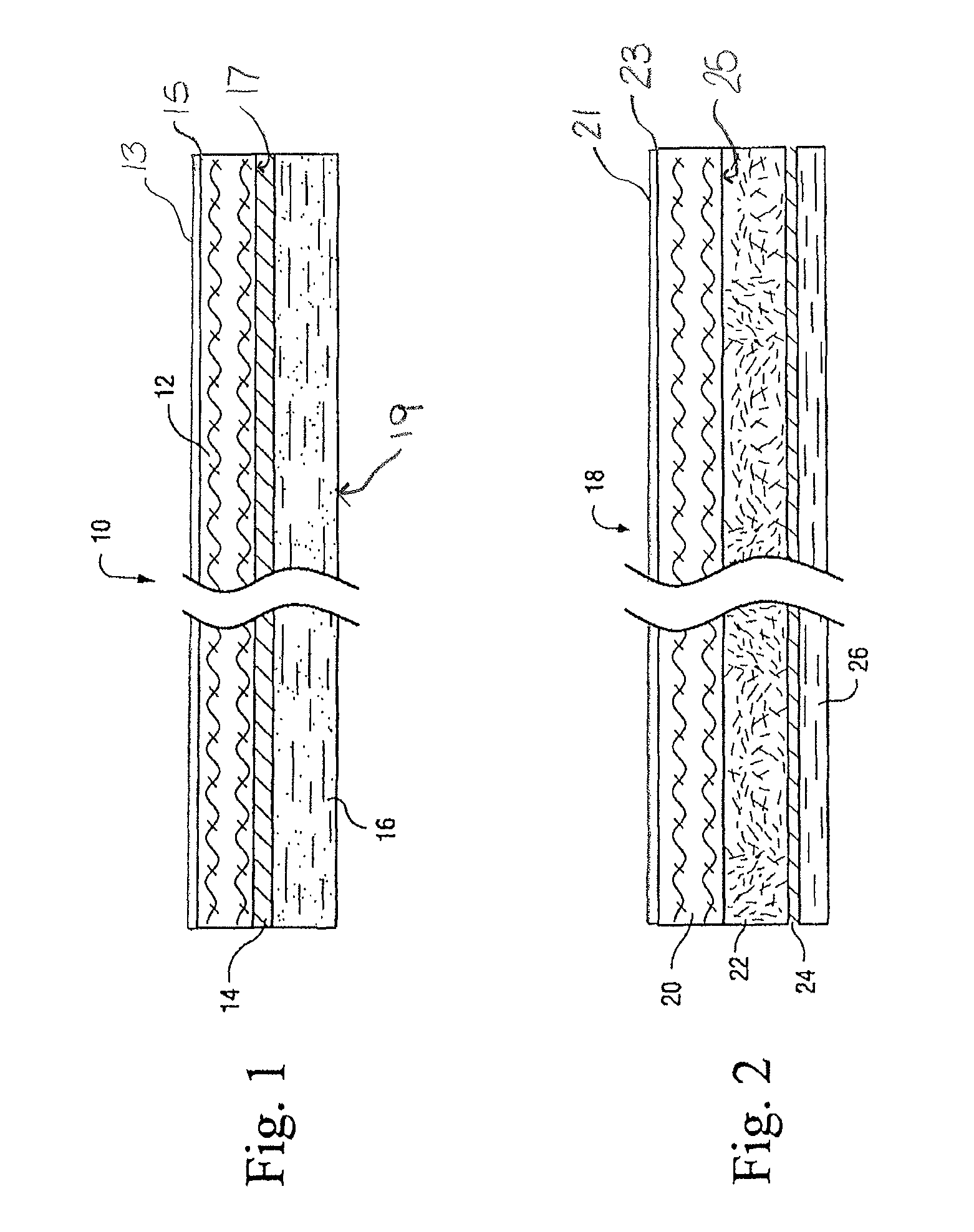
[0049]Referring now to FIG. 2, a second embodiment illustrates a cover 18 that includes an outer textile or face layer 20 similar to face layer 12, overlying an interior textile fabric layer 22 incorporating super-absorbent polymers {SAPS). The textile fabric layer 22 is preferably a suitable non-woven fabric enclosing the SAP's in an otherwise conventional fashion. The layer 22 in turn overlies an ePTFE film or membrane 24 similar to membrane 14 described in connection with FIG. 1. The inner layer 26 is a textile fabric that may be of a material similar to inner textile layer 16 described hereinabove. Use of SAPs in the intermediate fabric layer 22 minimizes the possibility of reabsorption of moisture back into the space below the cover.

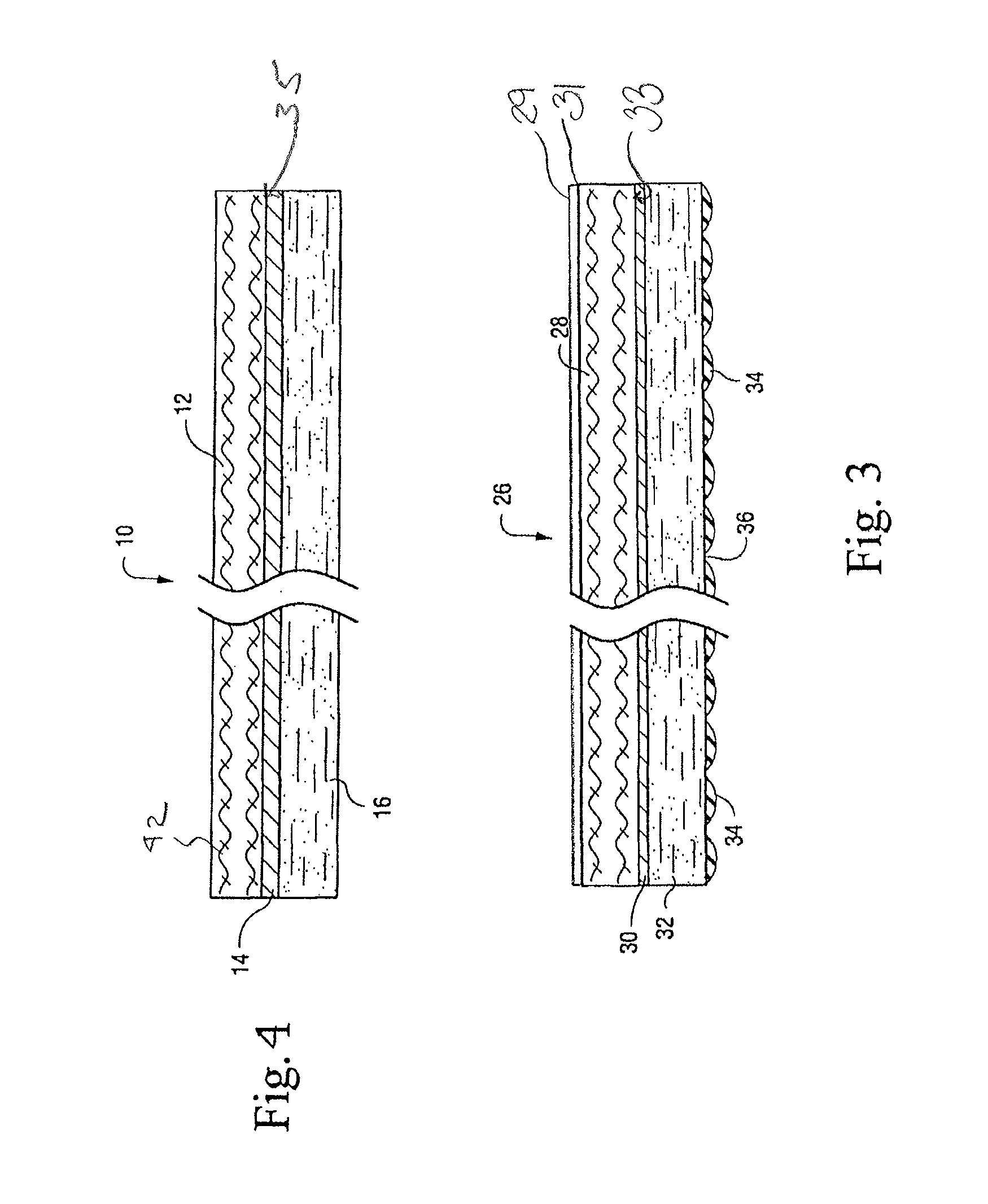
[0050]FIG. 3 illustrates a variation of the embodiment shown in FIG. 1. As such, the outer textile or face layer 28, intermediate membrane 30 and inner textile layer 32 are similar to the corresponding layers 12, 14 and 16 described hereinabove in c...


PUM

PropertyMeasurementUnit
lengthsaaaaaaaaaa
temperatureaaaaaaaaaa

Abstract

An enhanced protective cover includes a top and bottom textile layer and an air permeable, moisture-vapor-transmissive, expanded polytetrafluoroethylene membrane layer located between the two textile layers. The cover exhibits an MVTR rating of at least 4000 g / m2 / day. The protective cover also includes a top layer coating or fiber treatment of a nano-ceramic material designed to increase the durability of the cover and increase the resistance to abrasion and wear while also resisting environmental conditions including exposure to solar radiation, temperature and humidity. Alternatively, the upper layer of the protective cover may incorporate ceramic coated fibers or ceramic co-extruded fibers, or carbon nanotubes. The protective cover may also feature a fire resistant application. The top textile layer may also include a permanent, highly breathable and highly durable electro-static discharge feature added to the inside of the layer by laying down a carbon based printed pattern on the inside of the layer.

Description

CROSS-REFERENCE TO RELATED APPLICATIONS[0001]This application claims priority from U.S. Provisional Application Ser. No. 61 / 578,446 titled “Protected Covers And Related Fabrics” which was filed on Dec. 21, 2011, and is a continuation-in-part of U.S. patent application Ser. No. 11 / 482,105 filed on Jul. 7, 2006 and entitled “Protective Covers And Related Fabrics”, both of which are incorporated herein fully by reference.TECHNICAL FIELD[0002]The present invention relates to enhanced properties for protective covers for equipment typically stored outdoors such as airplanes, vehicles, munitions, weapons and weapons systems, electrical equipment and the like, and more particularly, to the construction of fabrics for such protective covers.BACKGROUND INFORMATION[0003]Protective covers are often used to protect equipment and parts in a wide range of environmental conditions. Corrosion and oxidation are of particular concern, especially in connection with vehicles, airplanes, munitions, weap...

Claims


Application Information

Patent Timeline
Patent Type & Authority Patents(United States)
IPC IPC(8): H05F3/00B32B27/34B32B5/02B32B27/12B32B27/32B32B5/30
CPCH05F3/00B32B5/022B32B5/024B32B5/026B32B5/30B32B27/12B32B27/322B32B27/34B32B2255/10B32B2255/02B32B2262/0261B32B2262/0276B32B2264/0257B32B2307/3065B32B2307/554B32B2307/584B32B2307/71B32B2307/714B32B2307/724B32B2307/73B32B2457/00B32B2571/00B32B2605/00B32B2255/26C23C16/511
Inventor THOMPSON, DONALD B.MOSER, LEON S.MCNAMARA, KATHERINE A.CROTTY, LEOSMITHIES, ALAN
Owner L&C PROTEC INC
Why Eureka
Try Eureka