Tubing saver rotator and method for using same

a rotator and tube technology, applied in the direction of drilling casings, drilling pipes, well accessories, etc., can solve the problems of tubing string wear, tubing holes, inefficient lifting or no lifting of fluids to the surface, etc., to minimize corrosion or contamination, and improve the pull strength of tubing

Active Publication Date: 2005-10-20
THOMSON MICHAEL A +1
View PDF3 Cites 12 Cited by
  • Summary
  • Abstract
  • Description
  • Claims
  • Application Information

AI Technical Summary

Benefits of technology

[0014] This invention relates to a tubing rotator assembly that sits in a casing head for purposes of suspending and rotating the tubing string in an oil well. The assembly includes a mandrel bowl or mandrel support that rests in the casing head. The mandrel bowl has an interior ledge with a surface on which a bearing may be placed. A tubing mandrel is partially contained within the interior of the mandrel bowl with one end exiting the bottom of the mandrel bowl and attached to the tubing string in the well, and the opposite end of the tubing mandrel exiting the top of the mandrel bowl. The tubing mandrel has a ledge which is rotatably mounted to the mandrel bowl. The ledge of the tubing mandrel is supported on the bearing, which bearing rests on the interior ledge of the mandrel bowl. The ledge of the tubing mandrel therefore engages and rotatably rides against the bearing. This arrangement allows the tubing to rotate by rotating the mandrel residing on the bearing disposed on the interior ledge of the mandrel bowl. The top of the tubing mandrel may be connected to a swivel, or be an integral part of the swivel, or connected to a union, or connected directly to a pump tee with the ability to partially or fully rotate in such a manner to allow one to rotate the tubing by turning the mandrel and or rotating part of the swivel. Normally, one would use a handle or pipe wrench to manually turn the mandrel or swivel or union that extends above the wellhead or, a device known in the art may be applied to automatically turn the mandrel or swivel or union. This design allows one to turn the tubing to the right and / or the left in a uniform manner or in a disproportionate manner that skips part of the rotation to benefit the pull strength of the tubing when removed after operation.
[0015] Seals are provided (but not necessary due to the conventional rubber seal above the bowl) to isolate the interior of the mandrel bowl from fluids from the well or outside the well before, during or after installation, thereby preserving any lubrication of the bearings and minimizing corrosion or contamination inside the mandrel bowl area. If these seals leak or are not provided, then the pump will continue to work since they are used to protect the bearings and not to seal the tubing fluids from the annular fluids. Seals may also be placed on the outside of the mandrel bowl or bowl plate, or inside the casing head, in order to provide additional sealing of the fluids between the casing and tubing strings. A bowl plate is positioned on top of the mandrel bowl with seals preferred to allow sealing between the bowl plate and the mandrel bowl and also between the bowl plate and the tubing mandrel. This allows the tubing rotator assembly to be a self contained unit with connection ends above and below the mandrel bowl to allow connection to the tubing string below the mandrel bowl and connection to a swivel, union, or other material to allow fluids to exit the wellbore from the tubing.

Problems solved by technology

The reciprocation or rotation of the rod string causes the rods to wear against the tubing, which may cause the tubing string to wear thin and develop a hole in the tubing.
Thus, the wear action can also lead to tubing holes due to corrosion since the inhibitors are wiped off.
These wear related holes in the tubing causes inefficient lift or no lift of the fluids to the surface and typically requires a rig to service the well.
Conventional casing heads are not typically able to be retrofitted to accommodate the necessary structure of a tubing rotator.
Further, the tubing rotators of the prior art typically use gears and drive assembly to rotate the tubing.
The rotators with continuous rotation commonly have more corrosion holes due to wear than a manual or intermittent rotator, and fail when a gear mechanism fails and may damage the rotator or wellhead assembly due to the torque imparted on the gears.
In addition, the positioning of a housing on top of the casing head is more costly and may involve the need to raise the pumping unit due to large spacing requirements between the casing head and the pump tee.
Wright's tubing hanger apparatus design and attached gear tubing rotator cannot all be removed or installed with the BOP stack attached to the wellhead.
Failure of these seals leads to immediate pumping operation failure and loss of bearing lubrication and corrosion protection.

Method used


Image

  • Tubing saver rotator and method for using same
  • Tubing saver rotator and method for using same
  • Tubing saver rotator and method for using same

Examples


Embodiment Construction

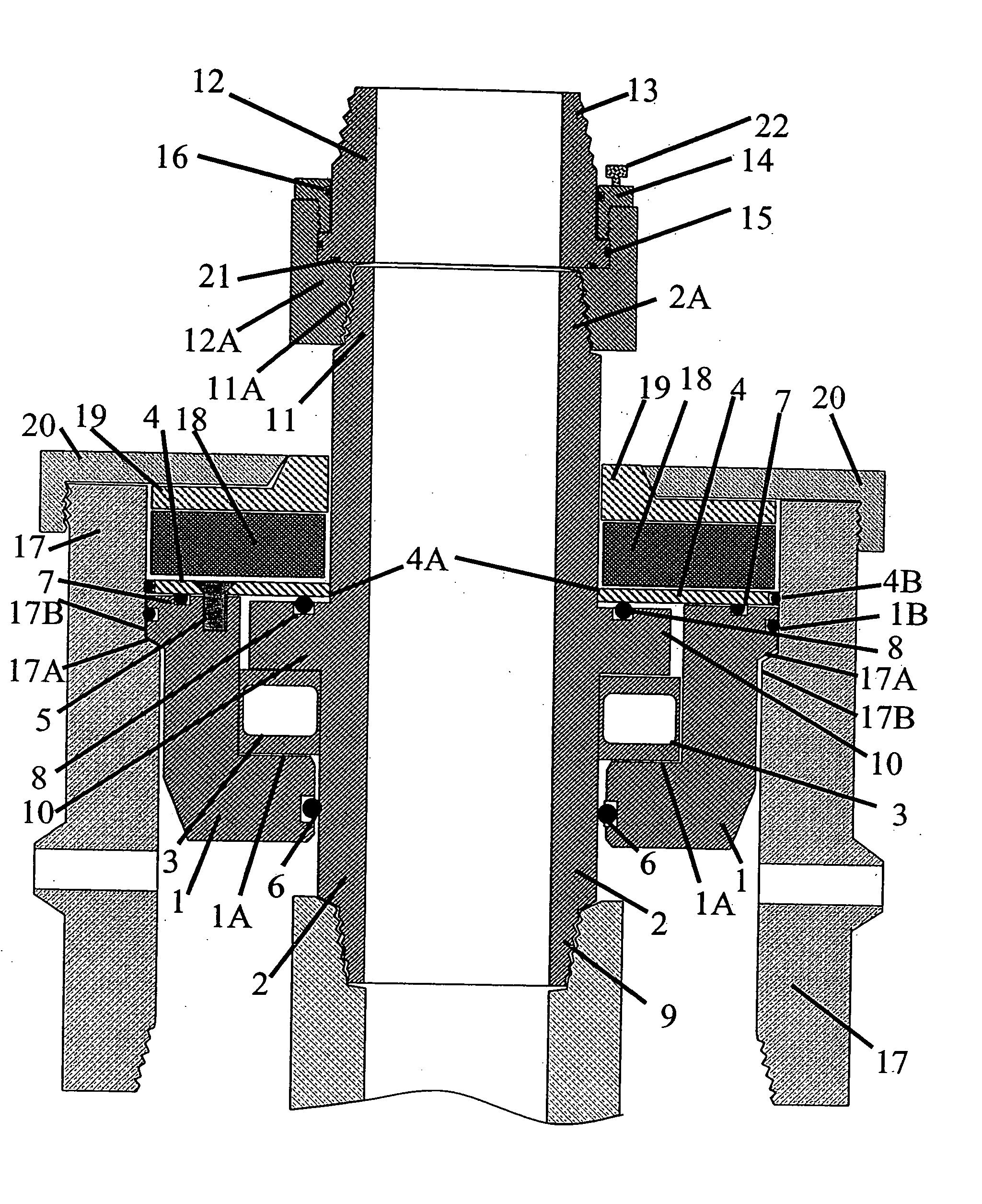
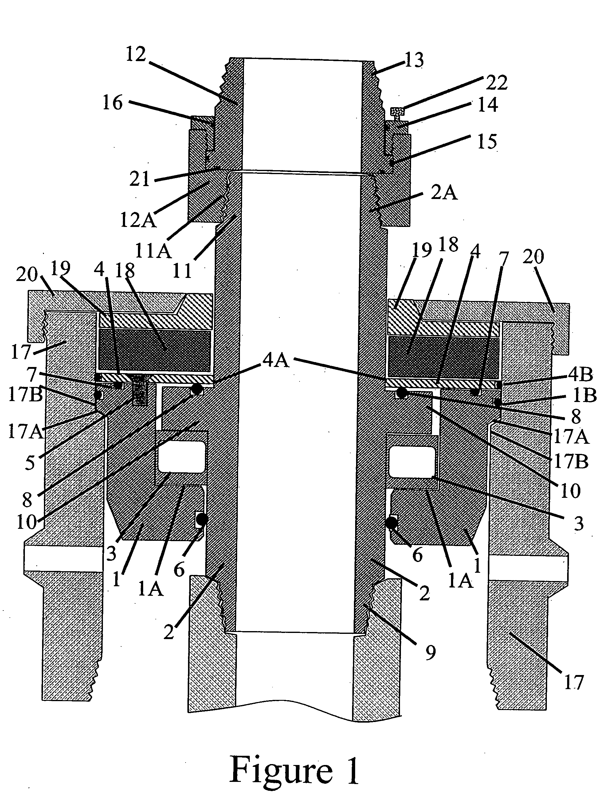
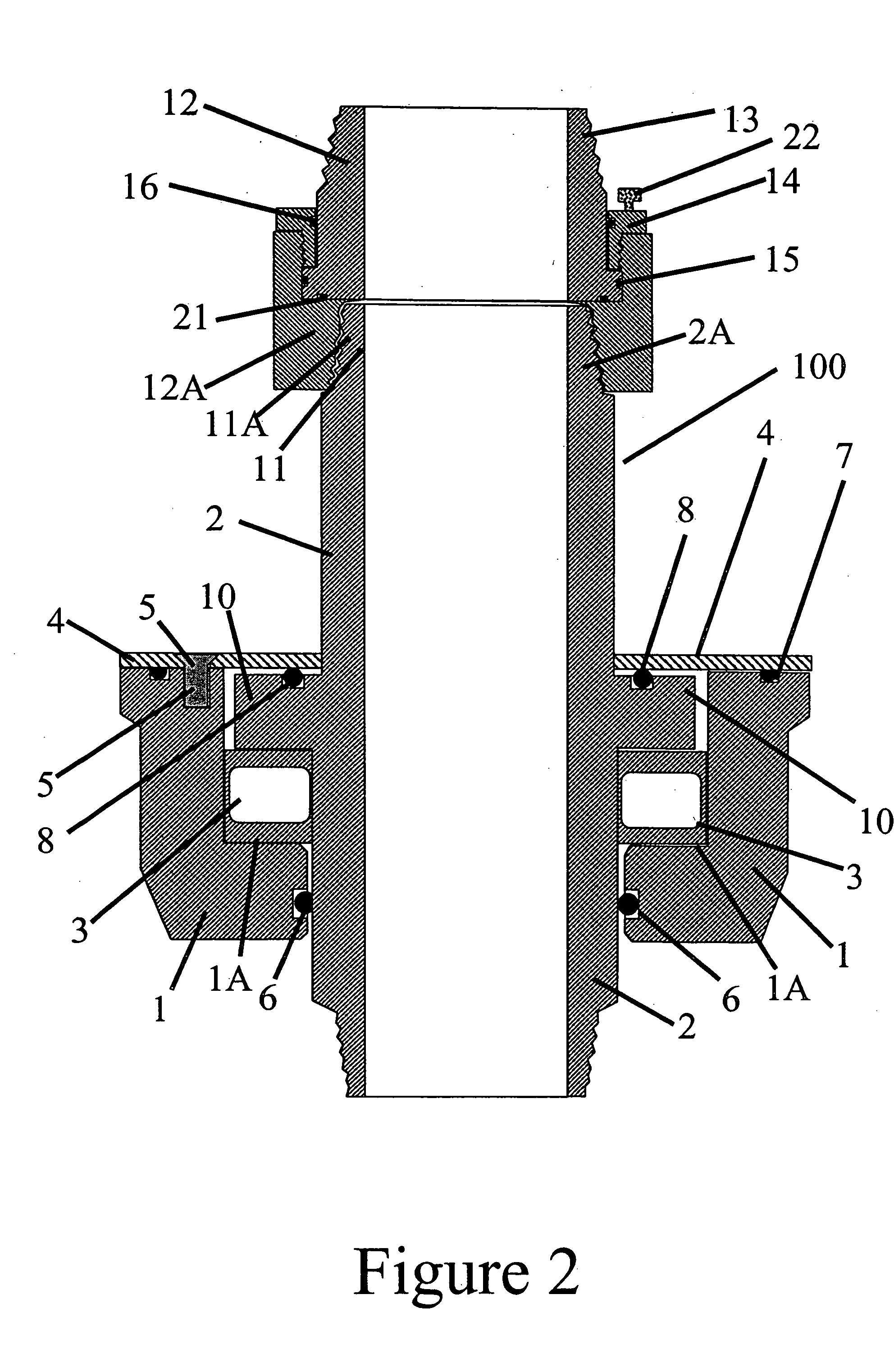
[0025]FIGS. 1-4 illustrate a preferred embodiment of a tubing saver rotator assembly 100 made in accordance with the present invention. Generally, the present invention is an apparatus for attachment in an existing casing head or a casing head modified to accept a bowl or ledge assembly. This apparatus having a surface, such as a bearing in which a tubing mandrel rests and allows one to rotate the tubing above the wellhead. It provides a low profile reducing the distance between the casing head and the pumping tee, which may eliminate the need for one to raise the pumping unit to fit on the rotator. In addition, the conventional seals above the bowl assembly have less chance of leaking fluids located between the casing and tubing due to the seals potentially installed in the present invention. In addition, if the conventional seals do start to leak, one can change the sealing elements without having to remove the pump tee, tubing rotator assembly 100 or tubing string (not shown) fro...


PUM


Abstract

The present invention relates to a tubing rotator assembly for attachment to an existing casing head for purposes of suspending and rotating a tubing string in an oil well. In the preferred embodiment, the tubing assembly includes a rotation surface, such as a bearing, in which a tubing mandrel rests and allows one to rotate the tubing manually above the wellhead. It provides a low profile reducing the distance between the casing head and the pumping tee, which may eliminate the need for one to raise the pumping unit to fit on the rotator. In addition, the conventional seals above the rotation surface have less chance of leaking fluids located between the casing and tubing due to the seals potentially installed in the present invention. In addition, if the conventional seals do start to leak, then one can change the packing rubber without having to remove the pump tee, tubing rotator assembly or tubing string (thus, not requiring a rig to change the sealing elements). The tubing assembly includes a mandrel bowl that rests inside the casing head. The mandrel bowl has an interior ledge in which the bearing may be placed on top of the ledge. A tubing mandrel is partially contained within the interior of the mandrel bowl with one end exiting the bottom of the bowl and attached to the tubing string in the well, and the opposite end of the tubing mandrel exiting the top of the bowl. The tubing mandrel has a ledge which is rotatably mounted to the mandrel bowl. Said ledge of the tubing mandrel is supported on the bearing, which bearing rests on the interior ledge of the mandrel bowl. The ledge of the tubing mandrel therefore engages and rotatably rides against the bearing. This arrangement allows the tubing to rotate by rotating the tubing mandrel resting on the bearing located inside the mandrel bowl.

Description

CROSS REFERENCES TO RELATED APPLICATIONS [0001] U.S. Provisional Application for Patent 60 / 371,393, filed Apr. 10, 2002, with title “Tubing Saver Rotator and Method for Using Same” which is hereby incorporated by reference. Applicant claims priority pursuant to 35 U.S.C. Par. 119(e)(i). Application is also a continuation-in-part of co-pending application Ser. No. 10 / 356,750, filed Feb. 3, 2003.[0002] Statement as to rights to inventions made under Federally sponsored research and development: Not Applicable BACKGROUND OF THE INVENTION [0003] 1. Field of the Invention [0004] This invention relates to a tubing rotator assembly that sits inside a casing head for purposes of suspending and rotating the tubing string in an oil well. [0005] 2. Brief Description of Prior Art [0006] A typical wellhead is often comprised of a casing head which engages or is otherwise mounted to a casing string contained within a wellbore of a well at the surface. A mandrel bowl is mounted to the casing head ...

Claims


Application Information

Patent Timeline
Patent Type & Authority Applications(United States)
IPC IPC(8): E21B33/04
CPCE21B33/0415
Inventor THOMSON, MICHAEL A.HART, PHILIP E.
Owner THOMSON MICHAEL A
Why Eureka
Try Eureka