Techniques for monitoring gear condition

a technology of gear condition and monitoring technique, which is applied in the direction of machine part testing, structural/machine measurement, electric/magnetic means, etc., can solve the problems of labor-intensive and expensive, difficult to retrofit existing equipment, and possible free fall of load, so as to reduce the need for instruments and facilitate the retrofitting of existing equipment

Active Publication Date: 2018-01-09
KONECRANES GLOBAL
View PDF13 Cites 6 Cited by
  • Summary
  • Abstract
  • Description
  • Claims
  • Application Information

AI Technical Summary

Benefits of technology

[0006]It is an object of the present invention to alleviate one or more of the problems identified above. Specifically, it is an object of the present invention to provide methods, equipment and computer program products that provide improvements in one or more areas, such as reduction of the necessary instrumentation, ease of retrofitting existing equipment, or the like.
[0011]The inventors have tested this hypothesis successfully and experimented with various concrete embodiments for putting the invention to practical use. Embodiments of the invention aim at monitoring condition, particularly relating to wear, of the system being monitored by methods or equipments according to embodiments of the invention. In particular, embodiments of the invention aim at reducing additional instrumentation, such as additional sensors and cabling, which are used for monitoring wear in many of the prior art techniques.
[0019]The invention offers a number of advantages over known vibration-sensing techniques. Unlike techniques which are based on sensing of mechanical vibrations, the present invention can be used without acceleration sensors or cabling for them. Likewise, the present invention can be used without a separate sensor for producing a trigger pulse for starting or synchronizing the measurement. In addition to eliminating the need for acceleration sensor and cabling thereto, the present invention eliminates some of their associated disadvantages, such as the sensitivity to vibration from external sources.
[0024]In some implementations the analysis in the frequency domain comprises conversion to a cepstrum. A cepstrum is the result of taking the Fourier transform (FT) of the logarithm of the estimated spectrum of a signal. A benefit of the cepstrum conversion is that harmonic overtones are reduced to their base frequencies. For instance, if a given source of vibration is known to vibrate at, say, 5.5 Hz, and the vibration is not purely sinusoidal, harmonic overtones of n*5.5 Hz, n being an integer >1, are also generated from the same source. Reducing the harmonic overtones to their base frequencies simplifies the task of detecting vibration sources whose condition has changed over time. This is because the task of associating base frequencies with the vibration sources is easier compared with the task of associating a complex mix of base frequencies and harmonic overtones with the vibration sources. Those skilled in the art will understand alternative algorithms exist for arriving at a physically equivalent result, which in this case is reduction of harmonic overtones to their base frequencies and the simplification of the task of mapping a set of frequencies to the sources of those frequencies.

Problems solved by technology

If the gear breaks catastrophically, free fall of the load is possible.
A problem with the prior art is the extensive instrumentation required to measure the currents and to detect the various rotation angles with sufficient precision, resolution and repeatability.
While it may be feasible to provide new equipment with such additional sensors and connections, retrofitting existing equipment is difficult, labor-intensive and expensive.

Method used


Image

  • Techniques for monitoring gear condition
  • Techniques for monitoring gear condition
  • Techniques for monitoring gear condition

Examples


Embodiment Construction

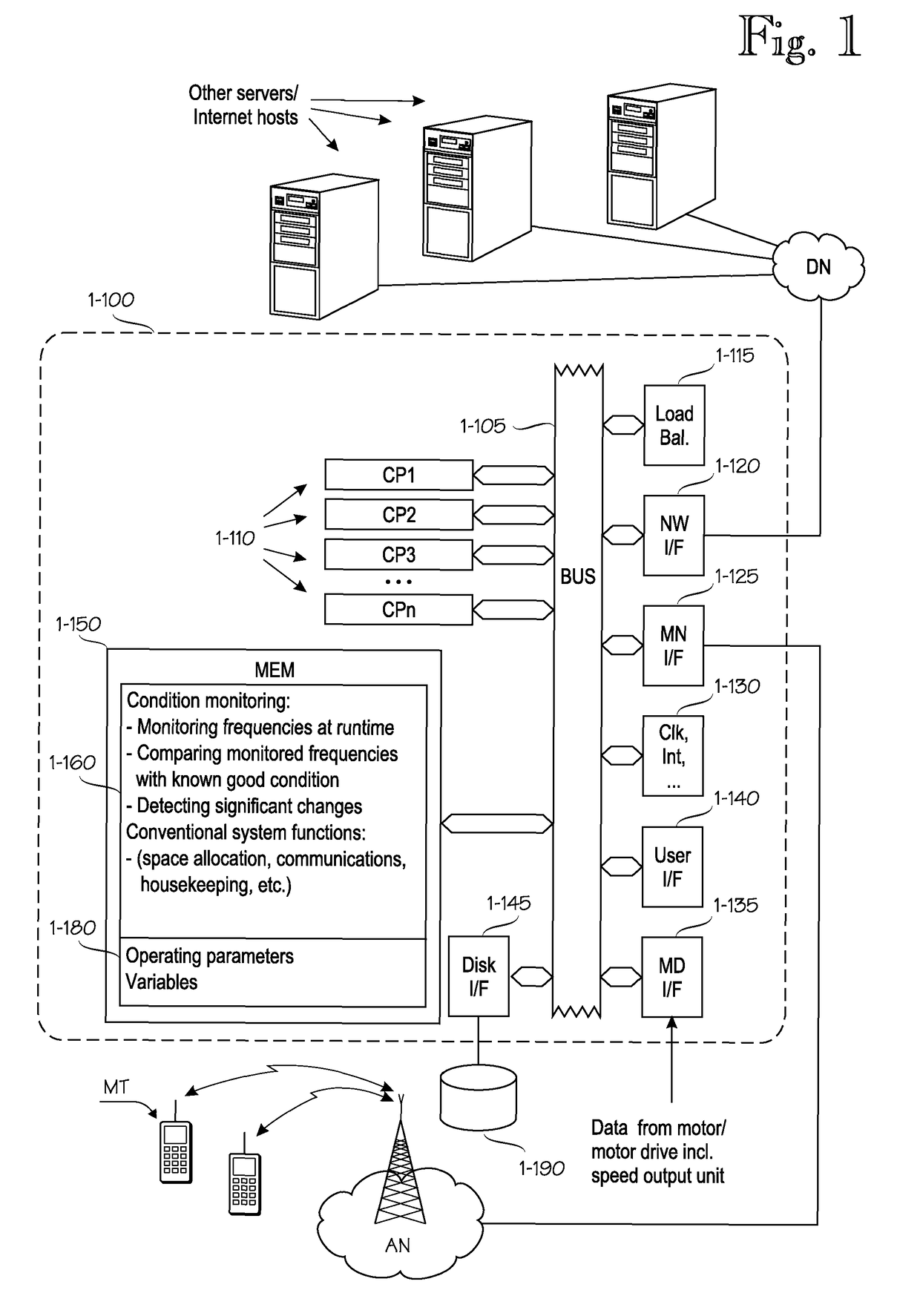
[0035]FIG. 1 shows an exemplary data processing architecture that can be programmed to perform the various data processing tasks relating to embodiments of the invention. In the following the data processing architecture will be referred to as a computer, but those skilled in the art will realize that the data processing architecture need not be implemented as a dedicated computer. Instead, several embedded techniques are possible, as are techniques in which the inventive functionality is installed on a data processing system that exists for other purposes.

[0036]The architecture of the computer, generally denoted by reference numeral 1-100, comprises one or more central processing units CP1 . . . CPn, generally denoted by reference numeral 1-110. Embodiments comprising multiple processing units 1-110 are preferably provided with a load balancing unit 1-115 that balances processing load among the multiple processing units 1-110. The multiple processing units 1-110 may be implemented ...


PUM


Abstract

Method / apparatus for performing the following acts on a system that includes an electrical motor followed by a gear, and a speed output unit: monitoring a first set of frequencies from the system over a measurement period when the system is in a known good operating condition; storing the first set of monitored frequencies or derivatives thereof as reference data in a long-term storage system; monitoring a second set of frequencies from the system over a measurement period when the system is in an unknown operating condition; comparing the second set of monitored frequencies with the first set of monitored frequencies in a frequency domain; in the frequency domain, detecting changes between corresponding frequencies resulting from the second set of monitored frequencies and the first set of monitored frequencies.

Description

FIELD OF THE INVENTION[0001]The present invention relates to predicting gear failure in connection with electrical motors, particularly in connection with electrical motors driven by motor drives.BACKGROUND OF THE INVENTION[0002]To provide a concrete, albeit non-restricting example, problems underlying the invention are described in connection with electrical drives that provide vertical movement or movement with a vertical component, such as electrical cranes, hoists or lifts. This is because the load being lifted or suspended affects the entire system of gears, axles and bearings, even in a steady-state condition when motion is stopped. A safety brake is typically installed on the primary or engine side of the gear. If the gear breaks catastrophically, free fall of the load is possible. Those skilled in the art will realize, however, that early prediction of gear failure is desirable in connection with virtually any electrical drives, regardless of direction of motion.[0003]In the...

Claims


Application Information

Patent Timeline
Patent Type & Authority Patents(United States)
IPC IPC(8): G01M13/02H02P29/032G01P3/44G01H1/00
CPCG01M13/021H02P29/032G01P3/44G01H1/006
Inventor MESIA, HEIKKIKEROVUORI, JUHANIHARRA, ILKKAJANTUNEN, AAPOSALOMAKI, JANNE
Owner KONECRANES GLOBAL
Why Eureka
Try Eureka