Heatable Flow-Through Measurement Cell

a flow-through measurement and gas analyzer technology, applied in the field of measurement cells, can solve the problem of relatively low thermal conductivity of materials, and achieve the effect of reducing instrumentation or the required apparatus and good thermal conductivity

Inactive Publication Date: 2012-08-02
SIEMENS AG
View PDF5 Cites 3 Cited by
  • Summary
  • Abstract
  • Description
  • Claims
  • Application Information

AI Technical Summary

Benefits of technology

[0012]It is therefore an object of the invention to reduce instrumentation or the required apparatus associated with known solutions for a measurement cell. This and other objects an advantages are achieved in accordance with the invention by providing a heatable flow-through measurement cell for a gas analyzer, comprising an inner tube that is made of corrosion-resistant material and is terminated at each end with a respective end piece and a radiolucent window held therein, each having an electrical heating apparatus for heating the end pieces, comprising an outer tube that is made of material with good thermal conductivity and surrounds the inner tube coaxially so as to form a narrow gap, and comprising thermal insulation that surrounds the outer tube, where the heating apparatuses are integrated in the end pieces or abut against the outside of the end pieces.
[0013]In accordance with the invention, the inner tube forms the corrosion-resistant inner wall of the measurement cell and consists of a material that is corrosion-resistant with respect to the measurement gas, such as high-grade steel, tantalum, polytetrafluoroethylene (PTFE) or a carbon fiber composite material (carbon). Such materials have a relatively low thermal conductivity. In conjunction with the thermal insulation lying thereon, the outer tube, which consists of a material with good thermal conductivity, such as aluminum or copper, ensures that there is a uniform distribution of heat in the axial direction, such that no considerable temperature gradient can form over the length of the inner tube. It therefore suffices to heat the tubular measurement cell merely at the ends, and therefore only two heating apparatuses are required. These are integrated in the end pieces that terminate the inner tube at both ends and are provided with windows, or abut against the end pieces from the outside. The gas connections required for supplying and discharging the measurement gas can be provided directly on the inner tube in the region of the ends thereof or in the end pieces. It is also possible, for example, for the measurement gas to be supplied via a gas connection in the center of the tube and to be discharged in both end regions.

Problems solved by technology

Such materials have a relatively low thermal conductivity.

Method used


Image

  • Heatable Flow-Through Measurement Cell
  • Heatable Flow-Through Measurement Cell

Examples


Embodiment Construction

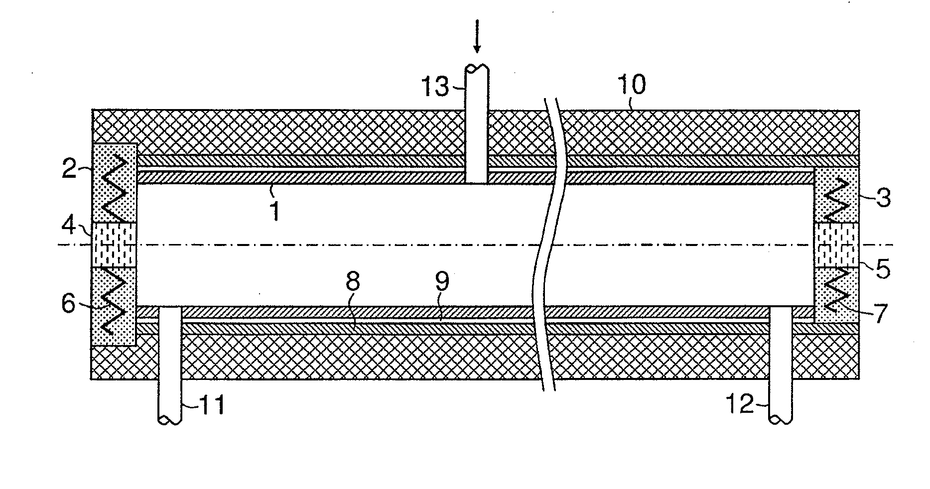
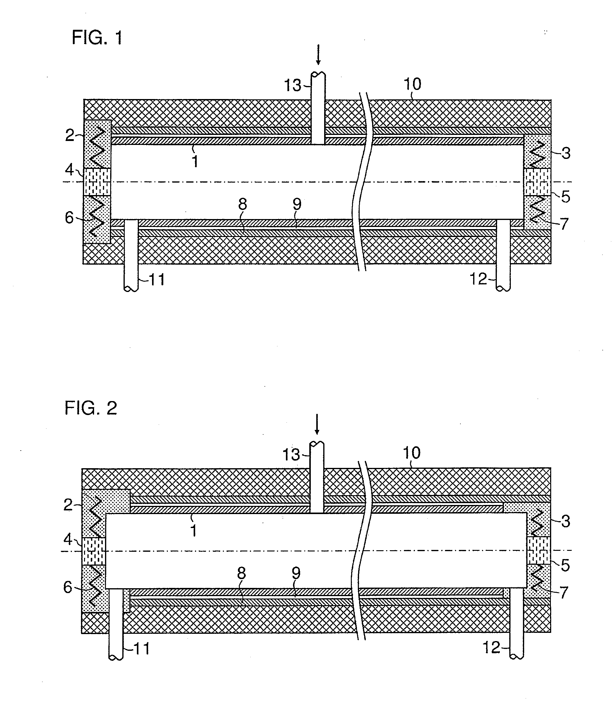
[0018]FIG. 1 shows a flow-through measurement cell for a gas analyzer (not shown here). The measurement cell consists of an inner high-grade steel tube 1, which is terminated at the ends thereof with two end pieces 2, 3 made of the same or a different corrosion-resistant material. Each of the two end pieces 2, 3 comprises a radiolucent window 4 and an electrical heating apparatus 6, 7. The heating apparatus 6, 7 can also be mounted on the outside of the respective end piece 2, 3. The high-grade steel tube 1 is surrounded coaxially by an outer aluminum or copper tube 8 which, as shown in the left-hand half of FIG. 2 using the example of the end piece 2, is held between the end pieces 2, 3 or, as shown in the right-hand half of FIG. 2 using the example of the end piece 3, rests on the end pieces 2, 3. In order to obtain a long measurement section and to simultaneously minimize the flow-through volume of the measurement cell, the length-to-diameter ratio of the high-grade steel tube 1 ...


PUM

PropertyMeasurementUnit
temperaturesaaaaaaaaaa
lengthaaaaaaaaaa
corrosion-resistantaaaaaaaaaa

Abstract

A heatable flow-through measuring cell for a gas analyzer having an inner tube made of a corrosion-resistant material, such as stainless steel, and is terminated at each end with a respective end piece and a radiolucent window held therein. The measuring cell also includes an electrical heating apparatus for heating each end piece, an outer tube that coaxially surrounds the inner tube so as to form a narrow gap and is made of material with good thermal conductivity, such as aluminum, and includes thermal insulation that surrounds the outer tube.

Description

CROSS-REFERENCE TO RELATED APPLICATIONS[0001]This is a U.S. national stage of application No. PCT / EP2010 / 058447 filed 16 Jun. 2010. Priority is claimed on German Application No. 10 2009 029 949.1 filed 19 Jun. 2009, the content of which is incorporated herein by reference in its entirety.BACKGROUND OF THE INVENTION[0002]1. Field of the Invention[0003]The invention relates to measurement cells and, more particularly, to a heatable flow-through measurement cell for a gas analyzer.[0004]2. Description of the Related Art[0005]EP 1 767 922 A2 discloses a flow-through measurement cell comprising a tube, which is terminated at each end with a respective heatable end piece and a radiolucent window held therein. The measurement gas is supplied at one end of the tube and discharged at the other, or is preferably supplied in the center of the tube and discharged at both ends of the tube.[0006]U.S. Pat. No. 4,205,550 discloses a flow-through measurement cell comprising an inner tube that is mad...

Claims


Application Information

Patent Timeline
Patent Type & Authority Applications(United States)
IPC IPC(8): G01N25/00
CPCG01N21/0332G01N21/3504G01N21/09G01N21/05
Inventor LUDWIG, MICHAEL
Owner SIEMENS AG
Why Eureka
Try Eureka