

Compact, modular, pump or turbine with integral modular motor or generator and coaxial fluid flow
a technology of modular motors and coaxial fluid flow, applied in the field of integrated sealless pumps and turbines, can solve problems such as the use of dynamic seals, the alignment problem of the motor or generator, and the source of leakage and other failure modes, so as to simplify the overall pump design, reduce the effect of instruments and safe shutting down the system
- Summary
- Abstract
- Description
- Claims
- Application Information
AI Technical Summary
Benefits of technology
Problems solved by technology
Method used
Image

Examples
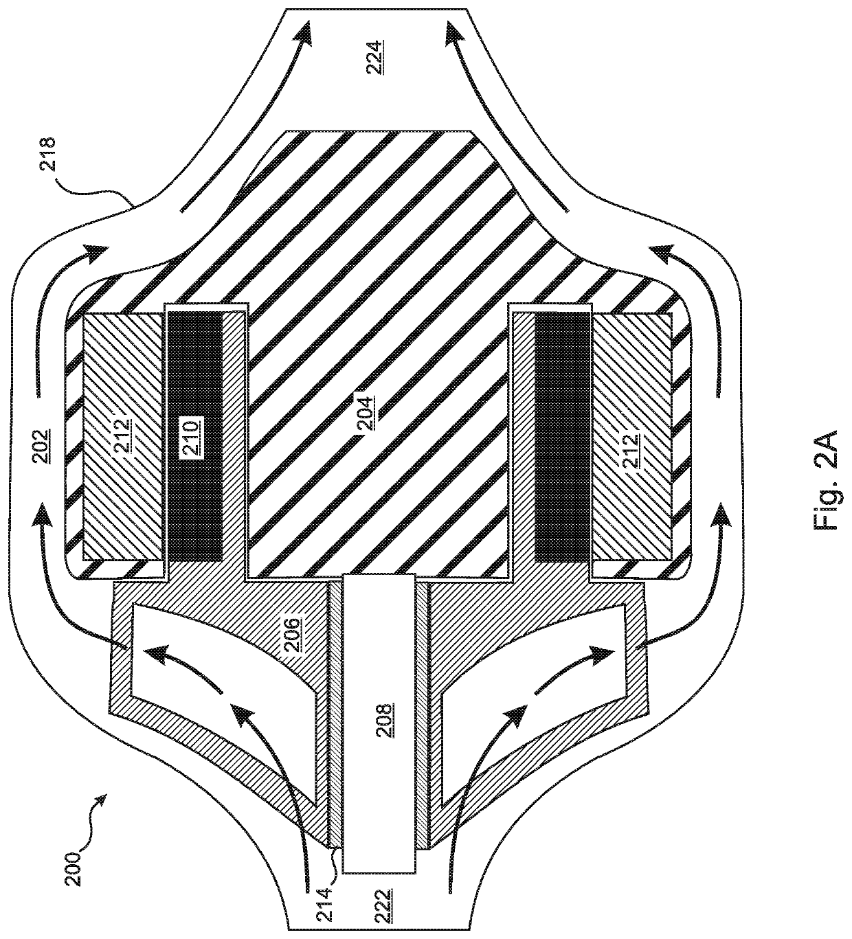
embodiment 200
[0094]The present invention is a “sealless” motor pump or sealless generator turbine that is configured as a module having a “concentric” flow design. As an example, a pump embodiment 200 of the present invention is illustrated in FIG. 2A. It can be seen in the figure that the housing 204 of the motor coils 212, i.e. the stator housing 204, is surrounded by the housing 218 of the module, forming an annular space 202 therebetween. According to the present invention, the working fluid is distributed about the annular space 202, either among a plurality of flow passages or through a single annular flow passage. The distribution of the working fluid in the annular space 202 can be symmetric about the stator housing 204. In the embodiment of FIG. 2A, the annular space 202 serves as an annular flow passage 202 through which the working fluid flows from the inlet 222 to the outlet 224.
[0095]In the embodiment of FIG. 2A, the annular flow passage 202 is in direct thermal contact with the hou...
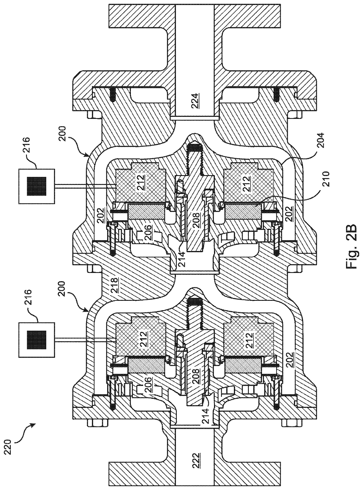
embodiment 220
[0097]More specifically, FIG. 2B illustrates a two-stage pump embodiment 220 wherein a central axis of the motor 212 in each stage 200 is substantially collinear with the stationary shaft 208 about which the rotor 206 is rotated, such that the process fluid from the rotor 206 flows axially over the stator housing 204 through the annular flow passage 202 formed between the stator housing 204 and the pump housing 218 in each stage 200. While only two stages 200 are shown in FIG. 2B for convenience of illustration, it will be understood that embodiments are extendable to an arbitrary number of pump stages 200.
[0098]In some multi-stage embodiments, the rotor 206 in each stage 200 is independently driven, such that the rotor speed of each stage 200 can be separately controlled. For example, a separate variable frequency drive (“VFD”) 216 can be dedicated to the control of each stage 200 of the pump.
[0099]In the embodiment of FIG. 2B, in each stage 200 of the pump 220 a plurality of perma...
PUM
 Abstract
Description
Claims
Application Information