Device for detecting liquid crystal module and method for detecting quantity of liquid crystal

a liquid crystal module and detection device technology, applied in the direction of force/torque/work measurement apparatus, instruments, material strength using single impulsive force, etc., can solve the problem of prolonging the service life of the detection device, and achieve the effect of convenient use, high pertinence and improved detection efficiency

Active Publication Date: 2018-01-09
TCL CHINA STAR OPTOELECTRONICS TECH CO LTD
View PDF16 Cites 0 Cited by
  • Summary
  • Abstract
  • Description
  • Claims
  • Application Information

AI Technical Summary

Benefits of technology

[0004]Starting from the above-mentioned technical problems in the prior art, the present disclosure proposes a device for detecting a liquid crystal module to improve the accuracy of abnormity detection of liquid crystal quantity in the liquid crystal module.
[0007]Through the device of the present disclosure, the collision units are connected to the top wall of the cover through the elastic members, so that the collision units can merely collide with predetermined positions of the panel. In this case, the positions where the panel has statistically maximum abnormity probability can be detected, thus achieving a high pertinency. Also, the detection efficiency is improved, and blind detection with low efficiency is avoided. The elastic members can also store a part of energy, so that collision can be completed without greatly vibrating the cover, thus prolonging the service life of the detection device. In addition, multiple collision units collide with the panel of a liquid crystal module to be detected in a dynamic and multi-point mode, so that whether liquid crystal bubbles appear in the product after collision can be determined in a better and more accurate way, and whether the quantity of liquid crystal added is abnormal can be determined more accurately.
[0008]In an embodiment, the elastic members are connected to the top wall of the cover in a movable mode. In this case, a detector can detect not only the predetermined positions of the panel, but also other positions as required. Thus the device can be conveniently used.
[0012]In an embodiment, the cover includes side walls extending downwards from the top wall, and a connector for fixing the liquid crystal module is arranged on each side wall. Through this structure, the liquid crystal module can be conveniently fixed in the cover, so as to bring convenience to the operation of a user.
[0013]In an embodiment, the device further includes a vibrating platform for applying vertical vibration, and the lower end of each side wall is connected with the vibrating platform through a fixing member. The vibrating platform can apply vibration with constant amplitude, so as to ensure the accuracy of detection. With the vibrating platform, the detector can easily use the device.
[0021]Compared with the prior art, the present disclosure has the following advantages. The collision units are connected to the top wall of the cover through the elastic members, so that the collision units can merely collide with predetermined positions of the panel. In this case, the positions where the panel has statistically maximum abnormity probability can be detected, thus achieving a high pertinency and improving the detection efficiency. In addition, the elastic members can be moved in the top wall of the cover to move the collision units, so that the detector can detect not only the predetermined positions of the panel, but also other positions of the panel as required. Thus the device can be conveniently used. Moreover, multiple collision units collide with a panel of a liquid crystal module to be detected in a dynamic and multi-point mode, so that whether liquid crystal bubbles appear in a product after collision can be determined in a better and more accurate way, and whether the quantity of liquid crystal added is abnormal can be determined more accurately.

Problems solved by technology

The elastic members can also store a part of energy, so that collision can be completed without greatly vibrating the cover, thus prolonging the service life of the detection device.

Method used


Image

  • Device for detecting liquid crystal module and method for detecting quantity of liquid crystal
  • Device for detecting liquid crystal module and method for detecting quantity of liquid crystal

Examples


Embodiment Construction

[0026]The present disclosure will be further illustrated below in conjunction with the accompanying drawings.

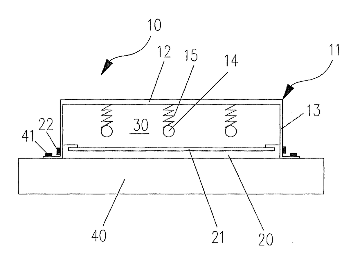
[0027]FIG. 1 schematically shows a device 10 for detecting a liquid crystal module according to the present disclosure (referred to as device 10 below). The device 10 includes a cover 11 and a plurality of collision units 14 connected to the top wall 12 of the cover 11 through elastic members 15 respectively.

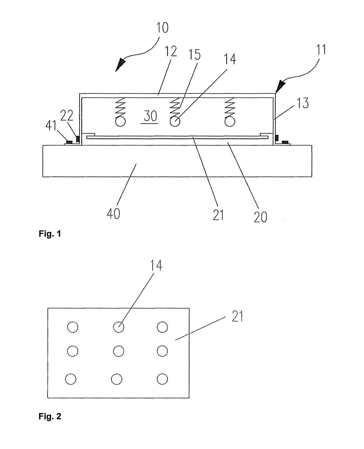
[0028]Before collision detection, the liquid crystal module 20 needs to be fixedly mounted in the cover 11. As shown in FIG. 1, when the mounting is completed, an accommodation space 30 is formed between the top wall 12 and the liquid crystal module 20. The collision units 14 are located in the accommodation space 30 and spaced from a panel 21 of the liquid crystal module 20 with a certain distance, so that the collision units 14 can move with large, enough amplitude. In this manner, sufficient impact can be applied to the panel 21 of the liquid crystal module. In an embo...


PUM

PropertyMeasurementUnit
thicknessaaaaaaaaaa
diameteraaaaaaaaaa
diameteraaaaaaaaaa

Abstract

The present disclosure relates to a device for detecting a liquid crystal module and a method for detecting the quantity of liquid crystal. The method includes a cover for fixedly accommodating the liquid crystal module. An accommodation space for accommodating collision units is formed between the liquid crystal module and the cover, the collision units being connected to the top wall of the cover through elastic members. The collision units are spaced from the liquid crystal module in a certain distance in a static status, and collide with a panel of the liquid crystal module through vibration of the cover in the vertical direction during detection. The device for detecting a liquid crystal module improves the detection efficiency.

Description

FIELD OF THE INVENTION[0001]The present disclosure relates to the field of detection of liquid crystal modules, in particular to a device for detecting a liquid crystal module. The present disclosure also relates to a method for detecting the quantity of liquid crystal by using the device.BACKGROUND OF THE INVENTION[0002]A thin film transistor liquid crystal display (TFT-LCD) controls penetration of light by using optical anisotropy and birefringent characteristic of liquid crystal molecules through a TFT switch and input of signal voltage so as to display images. In a liquid crystal display panel, a color filter substrate and a TFT substrate are boxed together through sealant, and a photo spacer is supported between the two substrates to form a certain cell gap, so that a liquid crystal filling space for filling liquid crystal is formed between the two substrates. The arrangement direction of the liquid crystal molecules in the liquid crystal filling space will be changed under the...

Claims


Application Information

Patent Timeline
Patent Type & Authority Patents(United States)
IPC IPC(8): G01N3/00G02F1/13G02F1/1333G01L5/00G01N3/30
CPCG02F1/1309G02F1/1303G02F1/133308G01L5/0028G01N2203/0085G01N3/30G01N2203/0019G01N2203/0033G01L5/0038
Inventor HUANG, XIAOYU
Owner TCL CHINA STAR OPTOELECTRONICS TECH CO LTD
Why Eureka
Try Eureka