
Sealing system and sealing ring

a sealing system and sealing ring technology, applied in the field of sealing systems, can solve the problems of inability to accurately position the sealing ring, damage to the sealing section,

Active Publication Date: 2018-01-16
SKF MARINE GMBH +1
View PDF22 Cites 0 Cited by
  • Summary
  • Abstract
  • Description
  • Claims
  • Application Information

AI Technical Summary

Benefits of technology

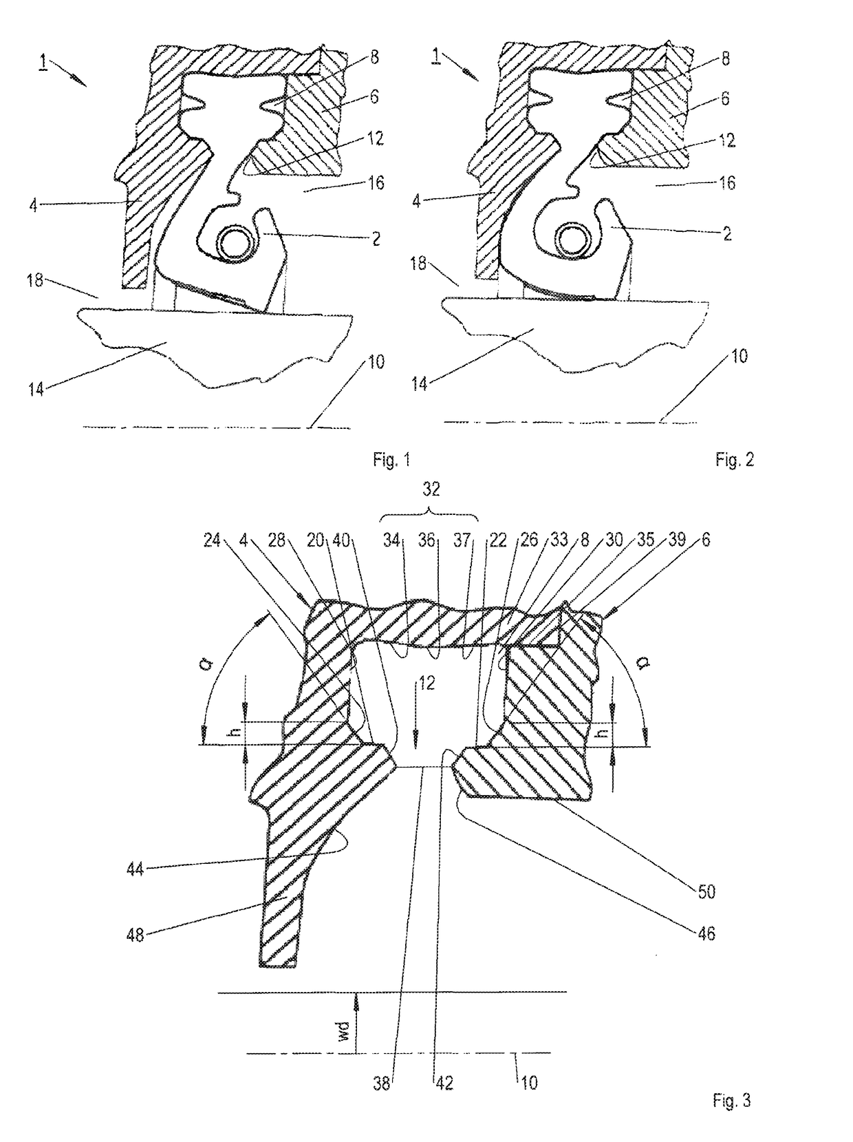
[0008]In order to achieve simple installation in both axial directions of installation and in order to achieve centering of the sealing ring on both sides, it is advantageous if both run-on surfaces and both inclined surfaces are equal in size and / or are oriented at the same angle relative to the system center axis. Preferably, the angle ranges from 40° to 50° relative to the symmetry axis. In particular, in each case the angle is 45° relative to the system center axis.
[0010]Furthermore, it has been shown to be advantageous if the clamping section has a greater radial extension and / or axial extension than the clamping space. Preferably, the clamping section and the clamping space have an identical radial extension or height, whereas the clamping section has a greater axial extension or width, preferably by 8% to 15%, in particular of 10% to 12%, than the clamping space. The clamping section preferably has a width-to-height ratio of 1.2 to 2.0, in particular of 1.5 to 1.7.
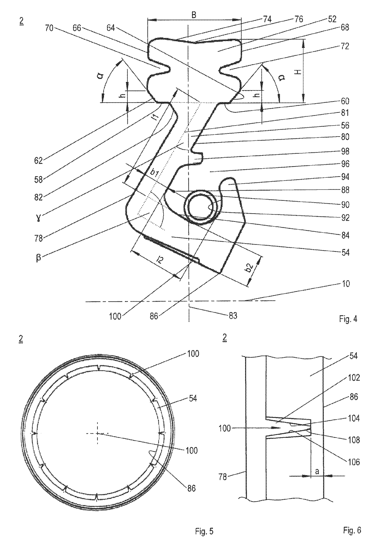
[0014]In order to protect the sealing lip in the case of overpressure, a multitude of lubrication pockets can be formed on the bottom side of the sealing lip, which lubrication pockets are open towards the low-pressure side of the sealing system. The lubrication pockets are preferably evenly distributed over the internal circumference and comprise an increased depth from their mouth to their base. As an alternative or in addition, they are wedge-shaped, rectangular or the like in the axial direction. In operation the lubrication pockets contain a fluid on the low-pressure side, wherein as a result of the increasing depth their respective mouth region is reduced in cross section. During the sudden rise in pressure on the high-pressure side, the narrowing mouth region prevents the fluid from being immediately pressed out of the lubrication pockets. The fluid quasi banks-up upstream of the mouth region in the lubrication pockets where it acts as a local supporting element, and consequently strong deformation of the sealing ring is prevented.

Problems solved by technology

Consequently, not only is the clamping section damaged, but also accurate positioning of the sealing ring is impossible.

Method used


Image

  • Sealing system and sealing ring
  • Sealing system and sealing ring
  • Sealing system and sealing ring

Examples


Embodiment Construction

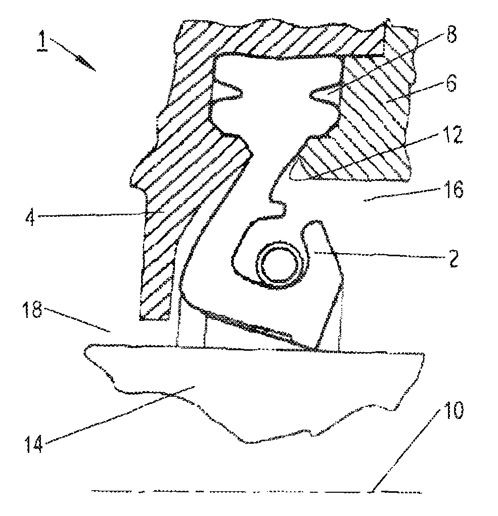
[0029]An exemplary sealing system 1 according to the invention, which sealing system 1 is shown in FIGS. 1 and 2, for sealing shafts 14 against liquid media, for example propeller shafts, impeller shafts, rudder stocks of ships, and the like, essentially comprises a sealing ring 2 and a first supporting ring 4 on the side of the housing, and a second supporting ring 6 on the side of the housing. The supporting rings 4, 6 delimit a clamping space 8 in which the sealing ring 2 is clamped. The sealing ring 2 leads from the clamping space 8 by way of an annular gap 12, which is situated radially inside, and sealingly rests against the shaft 14 to be sealed, or against a bearing bushing installed on the shaft 14, which shaft 14 rotates on its longitudinal axis that extends so as to be aligned with the system center axis 10. The sealing ring 2 in particular separates a high-pressure side 16 from a low-pressure side 18 or prevents liquid from flowing from the high-pressure side 16 to the l...


PUM


Abstract

A sealing system for sealing shafts against liquid media, for example propeller shafts, impeller shafts, rudder stocks of ships and the like. Opposing corner regions of the sealing system that are located radially inside of a clamping space, for clamping at least one sealing ring, are formed by inclined run-on surfaces that diverge when viewed radially from the inside towards the outside. For accommodation in the clamping space, a clamping section of the sealing ring comprises two opposite edge regions that are formed by inclined surfaces that correspond to the run-on surfaces.

Description

CROSS-REFERENCES TO RELATED APPLICATIONS[0001]This application claims the benefit of the German patent application No. 10 2013 017 816.9 filed on Oct. 22, 2013, German patent application No. 10 2013 017 817.7 filed on Oct. 22, 2013, and German patent application No. 10 2013 017 818.5 filed on Oct. 22, 2013, the entire disclosures of which are incorporated herein by way of reference.BACKGROUND OF THE INVENTION[0002]The invention relates to a sealing system for sealing shafts against liquid media, for example propeller shafts, impeller shafts, rudder stocks of ships, as well as to a sealing ring.[0003]Such a sealing system is, for example, shown in DE 41 41 999 C2, in DE 10 2011 018 584 A1, DE 10 2012 006 125 A1 and in U.S. Pat. No. 4,344,631 A. Each of these sealing systems comprises at least one sealing ring and supporting rings on the side of the housing, which supporting rings form a clamping space for clamping the sealing ring. The clamping space is open radially inside relative ...

Claims


Application Information

Patent Timeline
Patent Type & Authority Patents(United States)
IPC IPC(8): F16J15/322F16J15/3276F16J15/3268F16J15/3212F16J15/324F16J15/3244F16J15/3216F16J15/3252
CPCF16J15/3216F16J15/322F16J15/324F16J15/3276F16J15/3244F16J15/3252F16J15/3268F16J15/3212Y10S277/907F16J15/32
Inventor VON BERGEN, ERNST-PETERFANGAUF, CARLOSZIEMEN, LARSVON BORSTEL, DIETERRISTIC, IVANWUESTENHAGEN, GUIDO
Owner SKF MARINE GMBH
Learn More