
Spintronic generator

a spintronic generator and spintronic technology, applied in the field of permanent magnet rotational generators, can solve problems such as local environment temperature drop, and achieve the effect of enhancing the use of natural electron spin and abundant clean power

Active Publication Date: 2018-01-16
SEARL MAGNETRONIX
View PDF3 Cites 2 Cited by
  • Summary
  • Abstract
  • Description
  • Claims
  • Application Information

AI Technical Summary

Benefits of technology

The invention uses natural electron spin to create electrical power. The invention matches materials and magnetic waveforms to enhance the use of natural electron spin. This resonance of magnetic pulses coordinates different systems to provide clean and abundant power. The use of theZero Point Energy results in a drop in local environment temperature, which can be used as a motive force for harvesting electricity. The electricity can be harvested using standard induction pick up coils controlled by direct current motor controllers using an LRC tank circuit.

Problems solved by technology

A utilization of the Zero Point Energy results in a local environment temperature drop which can be one of the sources of motive force.

Method used


Image

  • Spintronic generator
  • Spintronic generator
  • Spintronic generator

Examples


Embodiment Construction

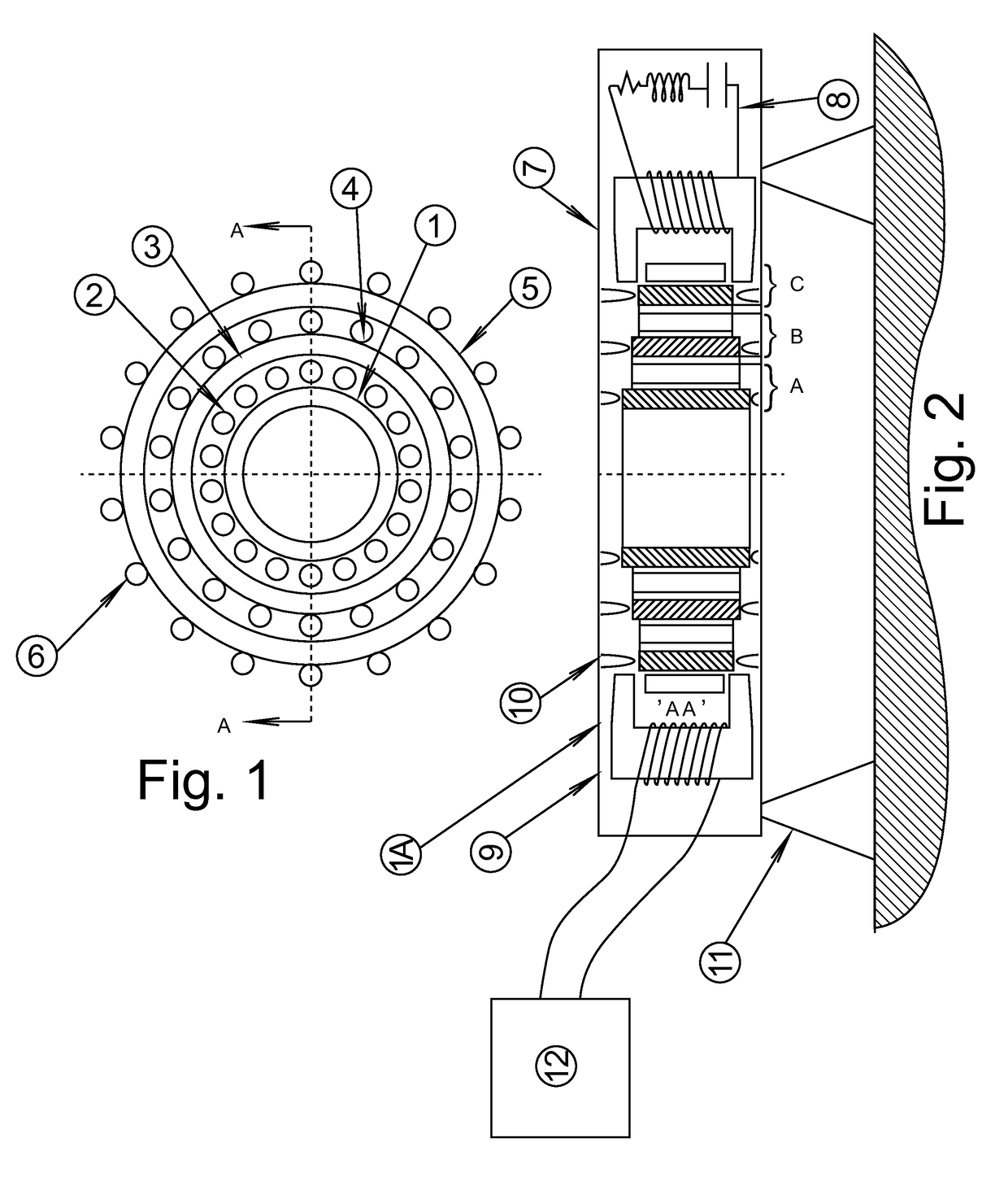
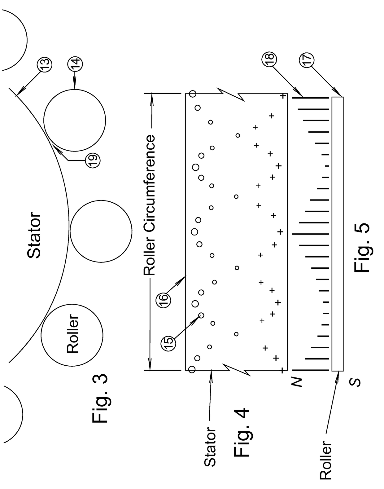
[0013]Referring now to FIG. 1 and FIG. 2, the generator is generally identified as number 1A. The generator can comprise 3 concentric ring Stators (though such number is not considered limiting) shown as reference numbers 1, 3, and 5. Concentric ring Stators 1, 3 and 5 can be securely attached to the frame enclosure 9. Individual Stators can be held in place with pins 10. Frame enclosure 9 can be preferably securely attached to a floor or a building, but can also be securely attached to other objects. Between the Stators are Rollers 2, 4, and 6. Rollers 2, 4 and 6 can be loosely held in place by magnetic force imprinted on both the Stators and Rollers. The Rollers are free to move about their respective Stators. Though not considered limiting, the core 7 of the coil can be an appropriate sized laminated Mu metal “C” section, preferably wrapped with a coil 8, which can be integrated with appropriate capacitors, inductors, and resistors in order to control the speed and output of the ...


PUM


Abstract

A spintronic generator that provides electrical power with the motive force of natural electron spin. The utilization of natural electron spin can be enhanced with carefully matched materials, weights, and magnetic waveforms which provide precise pulsed frequencies in resonance with the materials. This resonance of the magnetic pulses provides clean abundant power. A utilization of the Zero Point Energy results in a local environment temperature drop which can be one of the sources of motive force. The harvesting of electricity can be in standard induction pick up coils controlled by direct current motor controllers using an LRC tank circuit.

Description

[0001]This application claims the benefit of and priority to U.S. Provisional Patent Application Ser. No. 61 / 872,641, filed Aug. 31, 2014, which is incorporated by reference in its entirety.1. FIELD OF THE INVENTION[0002]This invention relates generally to electrical generators and in particular to permanent magnet rotational generators.2. BACKGROUND[0003]The Searl Effect provides a way for extracting clean and sustainable electrical energy. The Searl Effect Generator provides three uniquely magnetized fixed stator rings having patterns setup to generate continual motion of similarly magnetized cylindrical rollers. The rollers have both freedom of spin and rotation around the stator which generates both mechanical and electrical power.SUMMARY OF THE INVENTION[0004]The present invention relates to electron spin and the field of spintronics and provides for a spintronic generator. The present invention utilizes the application of large magnetic fields pulsed to micro sized magnetic fi...

Claims


Application Information

Patent Timeline
Patent Type & Authority Patents(United States)
IPC IPC(8): H02K15/12H02K37/00H02K23/60H02K15/03H02K16/00H02N11/00
CPCH02N11/008H02K16/00
Inventor MILLER, KIRK
Owner SEARL MAGNETRONIX
Learn More