
Cabin outflow valves having laterally-tapered sealing surfaces and cabin pressure control systems employing the same

a cabin outflow valve and sealing surface technology, applied in the field of lateral sealing valves, can solve the problems of significant technical challenges, inability to achieve further improvements in sealing surface conformity without a substantial increase in manufacturing costs, and the conventional approach to reduce outflow valve leakage is now largely exhausted, so as to reduce the profile height, reduce or eliminate the effect of leakage through the cabin outflow valv

Active Publication Date: 2018-01-23
HONEYWELL INT INC
View PDF5 Cites 0 Cited by
  • Summary
  • Abstract
  • Description
  • Claims
  • Application Information

AI Technical Summary

Benefits of technology

The patent is about a new kind of valve used in a vehicle, called a cabin outflow valve. The valve has special surfaces that help to seal it better when it is opened and closed. This helps to reduce leaks and improve the efficiency of the valve. The valve is designed to work with a special actuator and is used to control the air flow in a vehicle. This new design of the valve helps to make sure the air flows properly and helps to create a better seal.

Problems solved by technology

Modern cabin outflow valves can achieve relatively low leakage levels when in a closed position and subject to pressure loading during flight.
This presents a significant technical challenge as conventional approaches utilized to reduce outflow valve leakage are now largely exhausted or associated with certain undesirable tradeoffs.
However, manufacturing tolerances render further improvements in sealing surface conformity generally impractical without a substantial increase in manufacturing costs.
Stiffening the valve doors in this manner, however, increases manufacturing cost and adds undesired weight to the outflow valve.
Finally, a cabin outflow valve can be produced to include various reinforcement structures, which serve to apply a more uniform closing force to the valve doors and thereby reduce leakage; however, this again adds undesired weight, bulk, and manufacturing cost to the outflow valve.

Method used


Image

  • Cabin outflow valves having laterally-tapered sealing surfaces and cabin pressure control systems employing the same
  • Cabin outflow valves having laterally-tapered sealing surfaces and cabin pressure control systems employing the same
  • Cabin outflow valves having laterally-tapered sealing surfaces and cabin pressure control systems employing the same

Examples


Embodiment Construction

[0014]The following Detailed Description is merely exemplary in nature and is not intended to limit the invention or the application and uses of the invention. Furthermore, there is no intention to be bound by any theory presented in the preceding Background or the following Detailed Description.

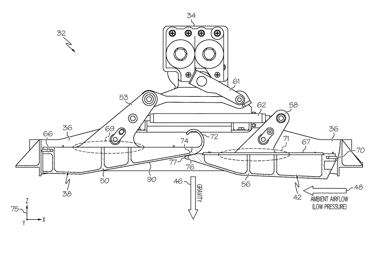
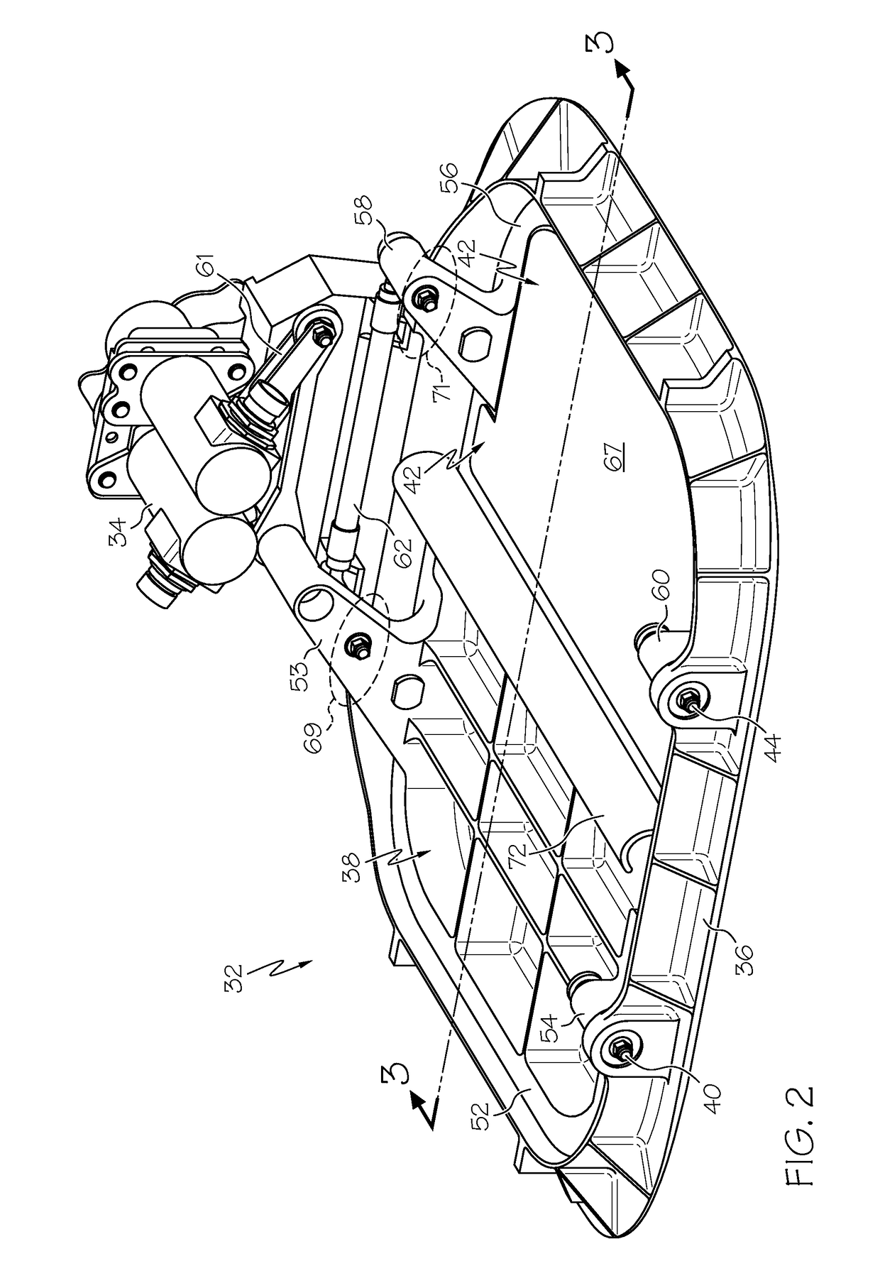
[0015]The following describes embodiments of a Cabin Pressure Control System (CPCS) including a cabin outflow valve having one or more laterally-tapered sealing surfaces, which enable the outflow valve to achieve exceptionally low leakage levels when closed and subject to pressure loading. Advantageously, the laterally-tapered sealing surface(s) can be produced without adding bulk, weight, or significant manufacturing cost to the cabin outflow valve. In an embodiment, the laterally-tapered sealing surfaces are characterized by a tapered profile height, which decreases with increasing proximity to the point at which the actuator applies a closing force when rotating the valve doors into a clo...


PUM


Abstract

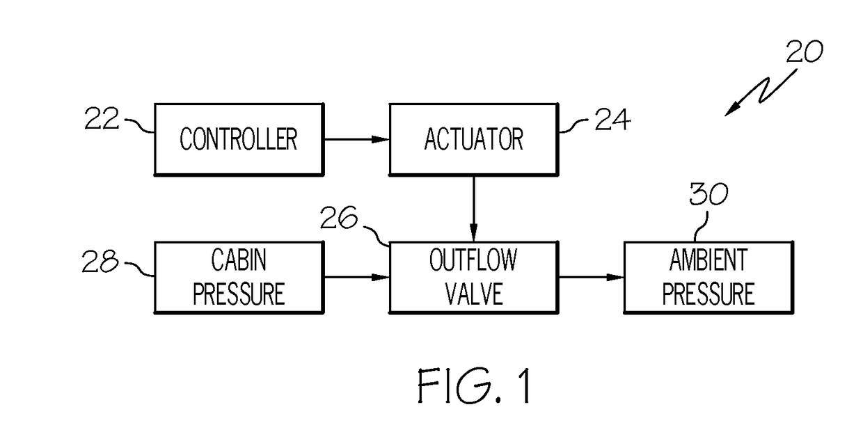
Embodiments of a cabin outflow valve having one or more laterally-tapered sealing surfaces are provided, as are cabin pressure controls system including cabin outflow valves. In one embodiment, the cabin outflow valve includes a frame and a first door, which is pivotally coupled to the frame and which is rotated by an actuator between open and closed positions. The first door includes, in turn, a torque input point at which the actuator applies a closing force when rotating the first door into a closed position. A laterally-tapered sealing surface extends along a lateral axis of the cabin outflow valve and has a profile height decreasing with increasing proximity to the torque input point. The laterally-tapered sealing surface helps to ensure the formation of a complete lateral seal when in the first door is rotated into the closed position to significantly reduce or eliminate leakage through the cabin outflow valve.

Description

TECHNICAL FIELD[0001]The present invention relates generally to laterally-sealing valves and, more particularly, to cabin outflow valves having laterally-tapered sealing surfaces, as well to cabin pressure control systems employing the same.BACKGROUND[0002]Aircraft are commonly equipped with cabin outflow valves, which are modulated during flight to maintain cabin air pressure within a desired range. The cabin outflow valve can include, for example, a frame, a first door (e.g., a first rectangular butterfly plate) pivotally mounted to a first portion of the frame, and a second door (e.g., a second rectangular butterfly plate) pivotally mounted to a second portion of the frame. The outflow valve may be mounted in the aircraft fuselage such that the first door is closer to the tail of the aircraft than is the second door; for this reason, the first door and the second door may be referred to as the “aft door” and the “forward door,” respectively. The aft and forward doors may be mecha...

Claims


Application Information

Patent Timeline
Patent Type & Authority Patents(United States)
IPC IPC(8): B64D13/02F16K1/226B64D13/04F16K1/22
CPCB64D13/04F16K1/2261F16K1/221F16K1/223
Inventor ROWE, STEVEN BRIANRYAN, WILLIAM F.BIRCHAK, DANTHOMAS, CHRISTOPHERKANG, ALBERT
Owner HONEYWELL INT INC
Learn More