
Low-profile antenna

A low-profile, antenna technology, applied in leaky waveguide antennas, antenna grounding switch structure connections, circuits, etc., can solve the problems of high profile antenna products and high antenna profiles in motion, and achieve reduced profile height, low profile, and reduced range Effect

Pending Publication Date: 2018-07-10
SHEN ZHEN KUANG CHI HEZHONG TECH LTD
View PDF3 Cites 0 Cited by
  • Summary
  • Abstract
  • Description
  • Claims
  • Application Information

AI Technical Summary

Problems solved by technology

However, the profiles of these mobile communication antenna products are relatively high
[0005] Aiming at the problem of high antenna profile in related technologies, no effective solution has been proposed so far

Method used


Image

  • Low-profile antenna
  • Low-profile antenna
  • Low-profile antenna

Examples


Embodiment Construction

[0024] The following will clearly and completely describe the technical solutions in the embodiments of the present invention with reference to the accompanying drawings in the embodiments of the present invention. Obviously, the described embodiments are only some of the embodiments of the present invention, not all of them. All other embodiments obtained by persons of ordinary skill in the art based on the embodiments of the present invention belong to the protection scope of the present invention.

[0025] According to an embodiment of the present invention, a low-profile antenna is provided.

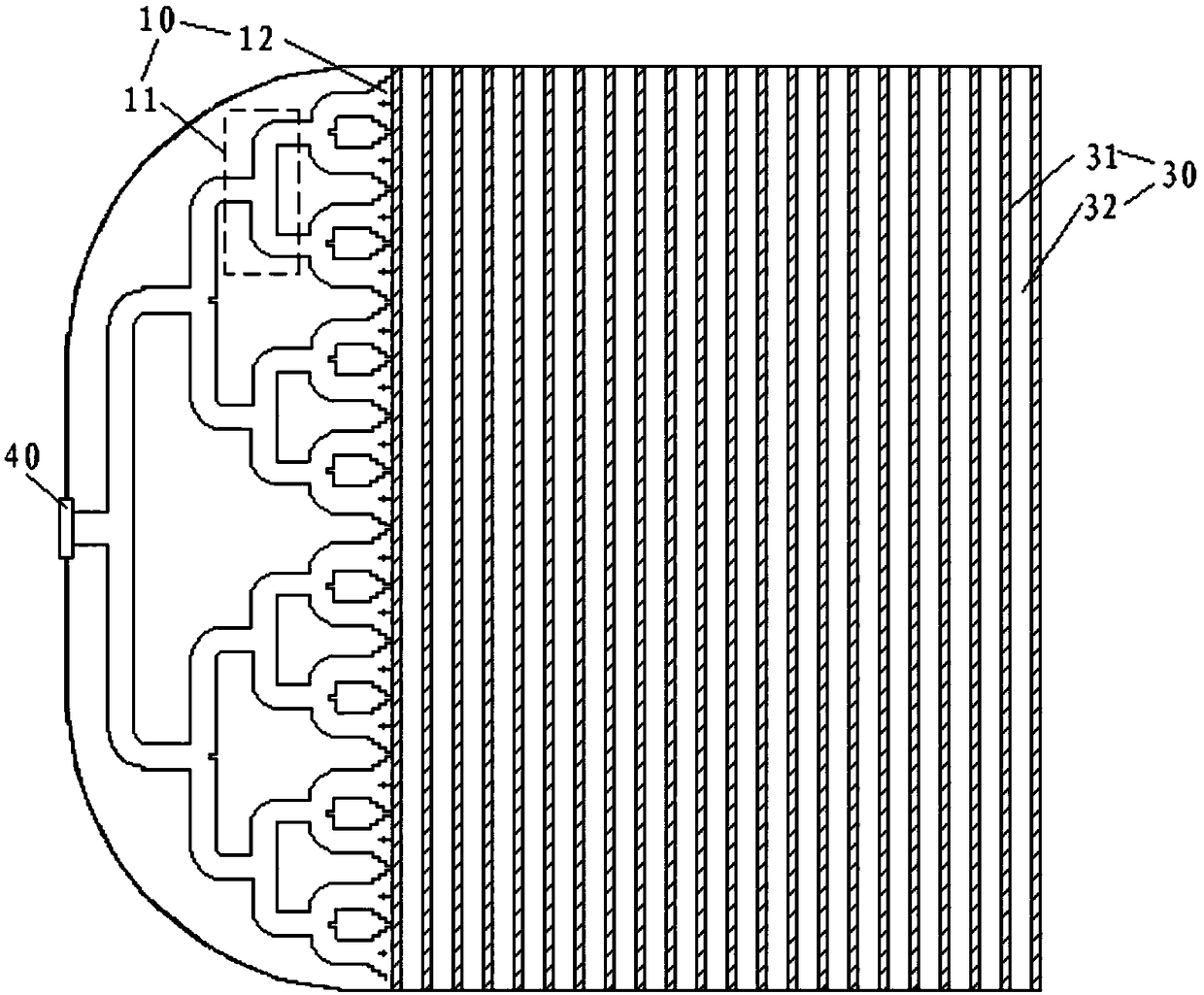
[0026] Such as figure 1 and figure 2 As shown, the low-profile antenna according to the embodiment of the present invention includes: a parallel plate waveguide 20 , and a slot radiation layer 30 , and the slot radiation layer 30 covers the upper substrate 21 of the parallel plate waveguide 20 . The thickness of the lower substrate 22 of the parallel plate waveguide 20 increases l...


PUM


Abstract

The invention discloses a low-profile antenna. The low-profile antenna comprises a parallel plate waveguide and a slit radiation layer. The thickness of a lower substrate of the parallel plate waveguide increases linearly so that an inclined surface is formed inside the parallel plate waveguide. The slit radiation layer covers an upper substrate of the parallel plate waveguide. The parallel platewaveguide is used for feeding the slit radiation layer. The low-profile parallel plate waveguide is adopted and the slit radiation layer is formed on the parallel plate waveguide, so the contour height of the antenna is reduced and the antenna has a lower profile. The inclined surface is formed inside the parallel plate waveguide, so the amplitude of gain attenuation is reduced when the scanning angle of the antenna changes.

Description

technical field [0001] The present invention relates to the technical field of antennas, in particular to a low-profile antenna. Background technique [0002] In a wireless communication system, in order to realize flexible and convenient means of communication, the antenna is required to have the characteristics of small size, light weight and full functions. [0003] In the existing antenna design, in order to realize beam scanning in both the horizontal direction and the pitch direction, the antenna needs to be able to rotate in both the horizontal direction and the pitch direction; technology to achieve beam scanning. As far as the current demand is concerned, there are many antenna products used in the mobile communication (satellite ground station communication in motion) system on the market. Communication in motion technology is to communicate with satellites anytime, anywhere on mobile carriers such as automobiles, ships, aircraft, and missiles. The antenna is on...

Claims


Application Information

Patent Timeline
Patent Type & Authority Applications(China)
IPC IPC(8): H01Q13/20H01Q1/50
CPCH01Q1/50H01Q13/20
Inventor 不公告发明人
Owner SHEN ZHEN KUANG CHI HEZHONG TECH LTD
Learn More