Modularized smart home-care lighting device

a smart home and lighting device technology, applied in the field of modular smart home care lighting devices, can solve the problems of difficult applications in a household or interfering environment, short detection range, and inconvenient use, and achieve the effect of convenient connection and disconnectibility

Inactive Publication Date: 2018-01-23
CHEN KAIPO
View PDF8 Cites 10 Cited by
  • Summary
  • Abstract
  • Description
  • Claims
  • Application Information

AI Technical Summary

Benefits of technology

[0008]In addition to combination of a lighting device with multiple known techniques of detection and remote surveillance and monitoring, the present invention uses a modularized structural design to allow a manufacture end to easily expand or subtract functions in a flexible manner by means of installation of different modules for products of different models so as to achieve the purpose of easy maintenance and also help maintain consistency of outside appearance in expanding the functions thereof, making it more convenient in practical applications.
[0010]The present invention uses a structure that is easily connectable and disconnectable to make function and maintenance thereof superior to similar products and also comprises a swappable assembly, which through connection arrangement may electrically drive all sorts of function and allows information of an external environment so acquired to be transmitted to the main control panel for decision making for applications, and being assisted by connection with related household appliances to make expansion of household environment perfect in an intelligent arrangement.

Problems solved by technology

Such a system needs an additional device used in combination therewith, making it imperfect and inconvenient in use.
However, a major drawback is that efficient and accurate detection of abnormality of a human body is generally not available and the range of detection is generally short, making it difficult for applications in a household or interfering environment.

Method used


Image

  • Modularized smart home-care lighting device
  • Modularized smart home-care lighting device
  • Modularized smart home-care lighting device

Examples


Embodiment Construction

[0026]The following descriptions are exemplary embodiments only, and are not intended to limit the scope, applicability or configuration of the invention in any way. Rather, the following description provides a convenient illustration for implementing exemplary embodiments of the invention. Various changes to the described embodiments may be made in the function and arrangement of the elements described without departing from the scope of the invention as set forth in the appended claims.

[0027]Better understanding of the present invention can be achieved according to a general detailed description of the present invention, as well as a preferred feasible embodiment thereof, in combination with the attached drawings. The present invention provides a modularized smart home-cue lighting device.

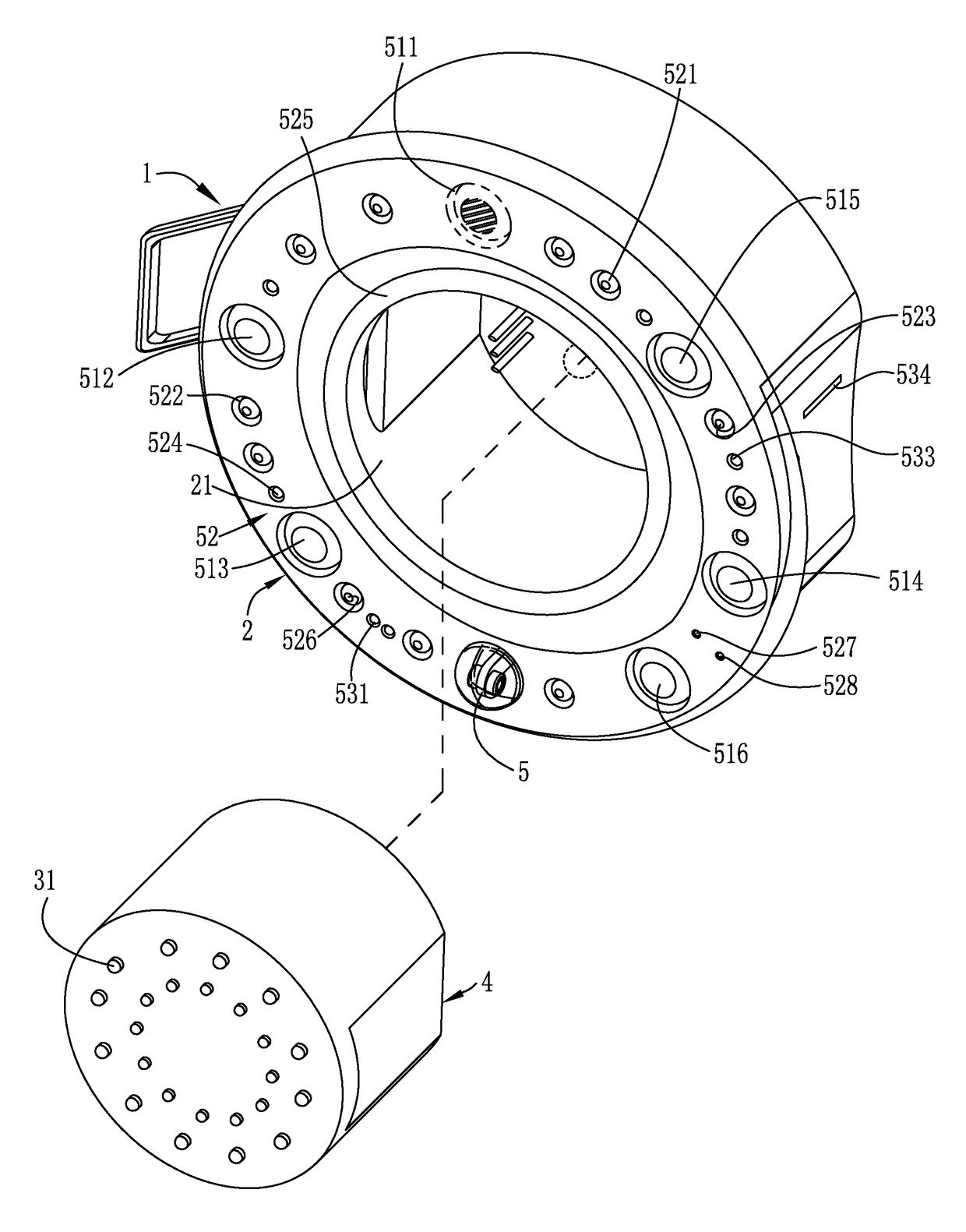
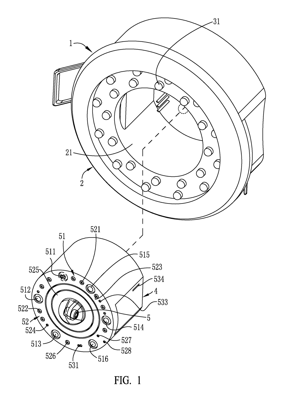
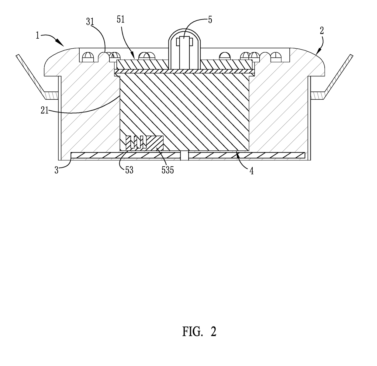
[0028]Shown in FIGS. 1-2 comprise: a lighting device (1), which comprises a base (2) and a swappable assembly (4). The base (2) is provided, in a central portion thereof, with contact terminals f...


PUM


Abstract

A modularized smart home-care lighting device includes a lighting device including a base and a swappable assembly. The base is provided therein with a plurality of LEDs and an insertion slot. The insertion slot allows for installation and connection of a swappable assembly that has a camera for panoramic surveillance and monitoring. The camera has a circumference in which a detection module that detects an environment outside the lighting device and an ancillary module corresponding to the detection module to provide reminder and alarm. The swappable assembly is readily inserted into the base to establish secured connection therewith. Through electrical connection with the main control panel in the swappable assembly, the lighting device is allowed for expansion for diverse functions, which in combination with automatic connection with household electrical appliances, allows family members to be well taken care of to achieve the purpose of smart home care.

Description

CROSS-REFERENCE TO RELATED APPLICATION[0001]This is a continuation-in-part of co-pending U.S. patent application Ser. No. 14 / 258,029 filed on Apr. 22, 2014 and owned by the present applicant.(a) TECHNICAL FIELD OF THE INVENTION[0002]The present invention relates generally to a modularized smart home-care lighting device, which comprises a swappable assembly having multiple functions and readily combinable with a lighting fixture to allow for expansion of utilization range in a household environment and improve overall utilization thereof.(b) DESCRIPTION OF THE PRIOR ART[0003]With the light-emitting diode (LED) technology getting mature in various applications, in addition to the development of techniques regarding energy saving and lighting, manufacturers also focus on the development of styles and functions of LED related devices available in the market to provide multiple functions associated therewith. One of the hottest applications is products that combine the Wi-Fi technology ...

Claims


Application Information

Patent Timeline
Patent Type & Authority Patents(United States)
IPC IPC(8): F21V17/00H04N7/18F21V33/00G08B5/36G08B13/196H04N5/232H04N5/225F21V23/04F21S9/02F21S8/06F21Y103/10F21Y115/10
CPCF21V17/002F21V33/0056F21V33/0076G08B5/36G08B13/19619H04N5/2251H04N5/2252H04N5/2256H04N5/2257H04N5/23238H04N7/183F21V33/0052F21Y2115/10F21S8/06F21S9/02F21V23/0471F21Y2103/10G08B13/19695G08B13/19697G08B19/00G08B21/24G08B25/08H04N23/50H04N23/56H04N23/57H04N23/51H04N23/60H04N23/698H05B47/105H05B47/19H05B45/20
Inventor CHEN, KAIPO
Owner CHEN KAIPO
Why Eureka
Try Eureka