Orthopedic apparatus for correcting rotational bone deformities and method for using the orthopedic apparatus

a technology of rotational bone deformation and orthopaedic device, which is applied in the direction of bone plate, bone plate, osteoporosis device, etc., can solve the problems of affecting the normal function of the bone, so as to promote the growth of the growth plate and correct the angular deformation

Active Publication Date: 2018-01-30
PEGA MEDICAL
View PDF9 Cites 3 Cited by
  • Summary
  • Abstract
  • Description
  • Claims
  • Application Information

AI Technical Summary

Benefits of technology

This patent describes an orthopedic apparatus for correcting angular deformation in bones. It consists of two main parts: a stationary segment and a mobile segment. The stationary segment is attached to the bone and extends at a predetermined angle, while the mobile segment is attached to the stationary segment and is designed to move around it. The mobile segment has fastening members that attach it to the bone, creating a connection that allows the bone to grow and correct the deformation. This apparatus can help promote healthy bone growth and correction of angular deformation in a safe and effective way.

Problems solved by technology

However, osteotomy procedures require making a large incision to create access to the bone for the surgeon to perform the bone cutting and realignment, thereby making the procedure substantially invasive.
In addition, the procedure can cause disruption of the adjacent musculature surrounding the bone as well as possibly damaging the neurovascular structures.
Procedures to cut and realign bones are associated with a long and painful rehabilitation period that can last several months.
The cut bone ends may not heal adequately and in such cases, further surgery may be necessary.
Implant failure is also a well documented complication of osteotomies.
Another concern is the accidental damage to the growth plate that can occur during the surgical realignment procedure, which can later inhibit healthy and normal limb growth.

Method used


Image

  • Orthopedic apparatus for correcting rotational bone deformities and method for using the orthopedic apparatus
  • Orthopedic apparatus for correcting rotational bone deformities and method for using the orthopedic apparatus
  • Orthopedic apparatus for correcting rotational bone deformities and method for using the orthopedic apparatus

Examples


first embodiment

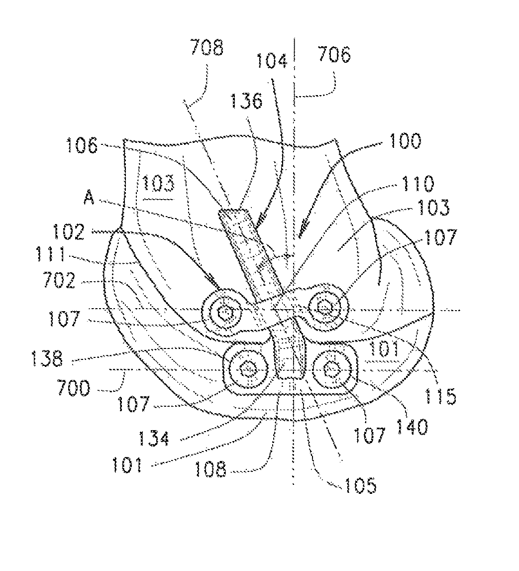
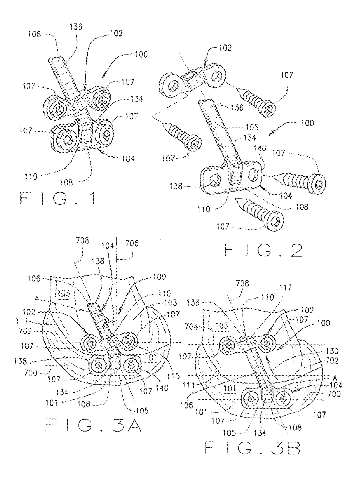
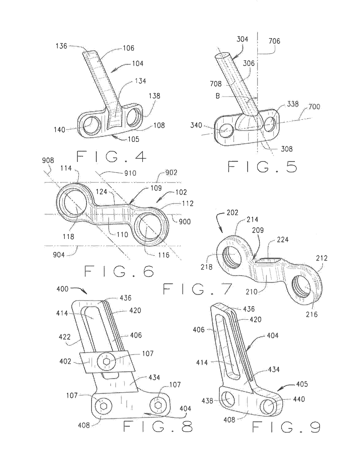
[0046]Referring to the drawings, embodiments of the orthopedic apparatus are illustrated and generally indicated as 100, 400, and 600 and in FIGS. 1-33. In general, as shown in FIGS. 1 and 2, the orthopedic apparatus, designated 100, includes a mobile segment 102 coupled to a stationary segment 104 with a plurality of fastening members 107 that are configured to secure respective portions of the mobile segment 102 and stationary segment 104 to different portions of a bone for a mammalian body. In particular, one embodiment of the stationary segment 104 shown in FIGS. 1, 2, and 4, designated 104, includes a substantially angular-shaped body 105 that defines an elongated track portion 106 configured to be coupled to the mobile segment 102 (FIGS. 1 and 2) and a fixed portion 108 secured to a portion of the bone for correcting the bone deformity. As shown, the track portion 106 defines a straight proximal part 134 integral or attached to the fixed portion 108 and an angled distal part 1...

second embodiment

[0054]Referring to FIGS. 8-10 and FIGS. 19-33, orthopedic apparatus, designated 400, is illustrated. As shown in FIG. 8, the orthopedic apparatus 400 includes a stationary segment 404 coupled to a mobile segment 402. As shown specifically in FIGS. 8 and 9, the stationary segment 404 defines a curved-shaped body 405 that includes a fixed portion 408 and a track portion 406 that extends at an angle from the fixed portion 408. In some embodiments, the track portion 406 of the stationary segment 404 is configured to be engaged to the mobile segment 402 and the fixed portion 408 of the stationary segment 404 is configured to be secured to the first bone portion 101 of an individual for correcting a rotational bone deformity as the first and second bone portions 103 grow over time and torsional growth of the growth plate 111 is promoted. As shown, the track portion 406 defines a proximal part 434 integral or attached to the fixed portion 408 and an angled distal part 436 formed at the fre...


PUM


Abstract

Embodiments of an orthopedic apparatus and method for using the orthopedic apparatus to correct rotational bone deformities are disclosed. Embodiments of the orthopedic apparatus include a stationary segment having a fixed portion engaged to a first bone portion and a track portion engaged to a mobile segment that is engaged to a second bone portion separated by the first bone portion by a growth plate such that the mobile segment migrates over time from a first position along the stationary segment to a second position along the stationary segment in such a way that torsional growth and correction of an angular deformity are promoted.

Description

FIELD[0001]This document relates to an orthopedic apparatus, and more particularly to an orthopedic apparatus and related method for correcting rotational bone deformities.BACKGROUND[0002]In orthopedics, rotational deformities of the bone along the lower portions of an individual can change the planar orientation of various respective reference planes for the hip, knee and ankle. For example, abnormal angulation of the femoral neck with respect to the transcondylar axis of the knee is referred to as femoral anteversion. In general, rotational deformities as discussed above may be defined as an abnormal angulation of a bone relative to a longitudinal axis.[0003]It is very common in infants to be born with femoral anteversion due to the position of the fetus inside the womb during pregnancy and can occur in up to 10% of children. In fact, femoral anteversion is the most common cause of children walking with their toes inward (in-toeing) in children older than 3 years of age. Although ...

Claims


Application Information

Patent Timeline
IPC IPC(8): A61B17/80
CPCA61B17/8023A61B17/8004A61B17/8061A61B17/8057A61B17/809
Inventor SAMPATH, JAYANTH SUNDARRAYES, FADYDUJOVNE, ARIEL RICARDO
Owner PEGA MEDICAL
Why Eureka
Try Eureka