Modular electrical connector and method of assembly

a technology of modular electrical connectors and connectors, applied in the direction of electrical apparatus, connection, coupling device connection, etc., can solve the problems of difficult to achieve the reliability of all the contacts assembled in the housing, contact deformation, and inapplicability to all contact configurations

Active Publication Date: 2018-01-30
TYCO ELECTRONICS LOGISTICS AG (CH)
View PDF13 Cites 4 Cited by
  • Summary
  • Abstract
  • Description
  • Claims
  • Application Information

AI Technical Summary

Benefits of technology

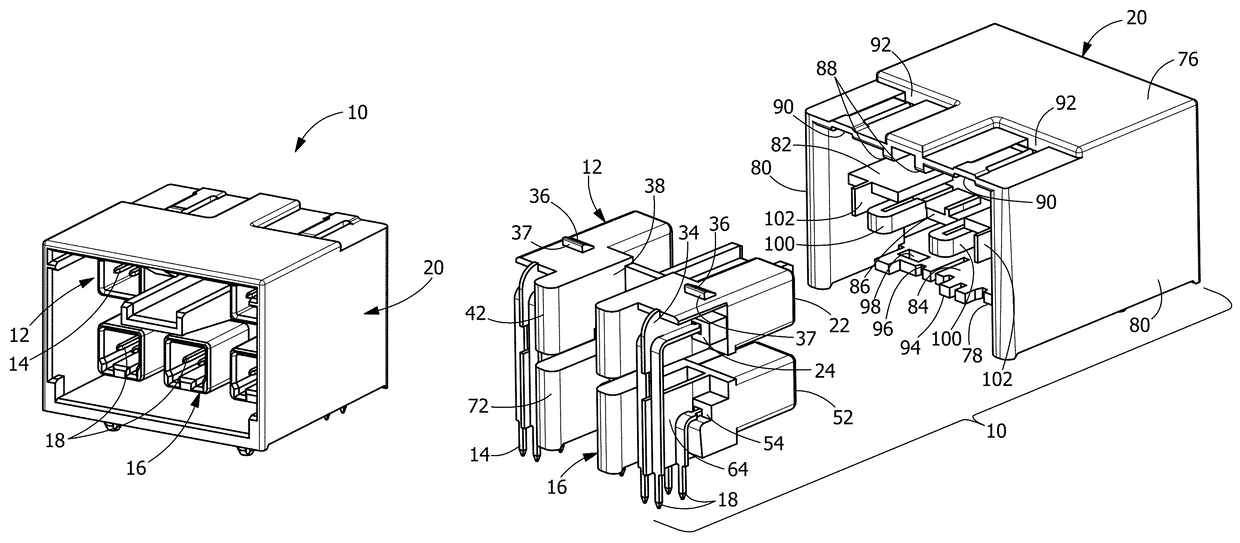
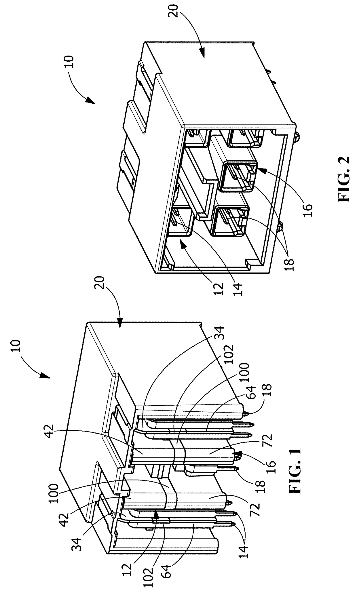
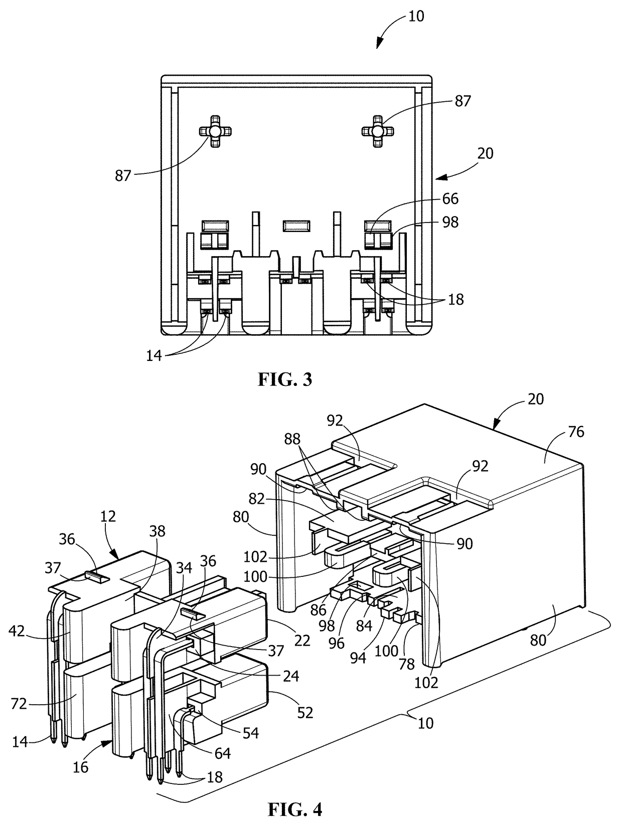
[0005]An embodiment is directed to a modular electrical connector assembly which includes a first housing, a second housing and a third housing. The first housing has first electrical contacts inserted therein. The first housing has first electrical contacts inserted therein. The second housing has second electrical contacts inserted therein. The third housing has a first opening for positioning the first housing therein and a second opening for positioning the second housing therein. First projections extend from a contact receiving end of the first housing in a direction away from a mating end of the first housing. The first projections provide a surface which allows an operator or automated machinery to engage the first housing and insert the first housing in the first opening of the third housing. The second projections extend from a contact receiving end of the second housing in a direction away from a mating end of the second housing. The second projections provide a surface which allows an operator or automated machinery to engage the second housing and insert the second housing in the second opening of the third housing.

Problems solved by technology

However, achieving reliability of all the contacts assembled in the housing is difficult due to space requirements and inability for conventional tooling to interact with the contacts to facilitate the bending thereof.
However, this is not practical for all contact configurations as the pressing force acting on the contacts may be large, causing the contacts to deform.

Method used


Image

  • Modular electrical connector and method of assembly
  • Modular electrical connector and method of assembly
  • Modular electrical connector and method of assembly

Examples


Embodiment Construction

[0016]The description of illustrative embodiments according to principles of the present invention is intended to be read in connection with the accompanying drawings, which are to be considered part of the entire written description. In the description of embodiments of the invention disclosed herein, any reference to direction or orientation is merely intended for convenience of description and is not intended in any way to limit the scope of the present invention. Relative terms such as “lower,”“upper,”“horizontal,”“vertical,”“above,”“below,”“up,”“down,”“top” and “bottom” as well as derivative thereof (e.g., “horizontally,”“downwardly,”“upwardly,” etc.) should be construed to refer to the orientation as then described or as shown in the drawing under discussion. These relative terms are for convenience of description only and do not require that the apparatus be constructed or operated in a particular orientation unless explicitly indicated as such. Terms such as “attached,”“affi...


PUM


Abstract

A modular electrical connector assembly and method of assembly. The modular electrical connector assembly includes a first housing, a second housing and a third housing. The first housing has first electrical contacts inserted therein. The first housing has first contact isolation walls positioned between adjacent first electrical contacts. The second housing has second electrical contacts inserted therein. The second housing has second contact isolation walls positioned between adjacent second electrical contacts. The third housing has a first opening for positioning the first housing therein and a second opening for positioning the second housing therein. The third housing has third contact isolation walls. Respective first contact isolation walls, second contact isolation walls and third contact isolation walls align to provide separation between adjacent first electrical contacts and separation between adjacent second electrical contacts.

Description

FIELD OF THE INVENTION[0001]The invention is directed to a modular electrical connector assembly and method of assembly. In particular, the invention is directed to a modular electrical connector assembly that allows for the bending of the contacts and insertion of the contacts into the modular electrical connector assembly utilizing convention tooling.BACKGROUND OF THE INVENTION[0002]Connectors generally have a large number of conductive contacts aligned in a dielectric housing thereof. Such connector must be designed to fulfill requirements of proper alignment, engagement and coplanarity of the contacts assembled in the housing. One way to assemble contacts of conventional connectors is to insert the contacts into contact receiving passageways of the housing and bend the tails of the contacts to properly position the tails for mating to a mating circuit board. However, achieving reliability of all the contacts assembled in the housing is difficult due to space requirements and ina...

Claims


Application Information

Patent Timeline
Patent Type & Authority Patents(United States)
IPC IPC(8): H01R13/514H01R13/424H01R43/20H01R13/631
CPCH01R13/514H01R13/631H01R13/424H01R43/20H01R13/506H01R13/518
Inventor CHALAS, GUADALUPEHALL, JOHN WESLEY
Owner TYCO ELECTRONICS LOGISTICS AG (CH)
Why Eureka
Try Eureka