
Eureka
For R&D, Eureka makes reading and utilizing patents & technical documents easy.
Eureka AIR
Designed for self-driven R&D workflows. Generate viable solutions, solve complex R&D challenges, empower your innovation with AI.

Eureka Materials
Designed for material experts only. Revolutionize your material R&D, from search, analyze, to developing new materials.

TechResearch
Generate reliable direction feasibility study reports for your R&D in just a few steps.

TechSeek
Discover and master advanced knowledge NOW. Basics, ideas, possibilities, all at once.

TechMind
As an expert in R&D Theories, TechMind can generates customized viable solutions instantly.

TechRisk
Analyze your overall solution with one click, know your potential R&D risks in advance.

TechMonitor
Get weekly tech updates, stay abreast of the latest tech innovations and key insights.
Thermal valve in upstream oil and gas
- Summary
- Abstract
- Description
- Claims
- Application Information
AI Technical Summary
Benefits of technology
Problems solved by technology
Method used
Image

Examples
Embodiment Construction
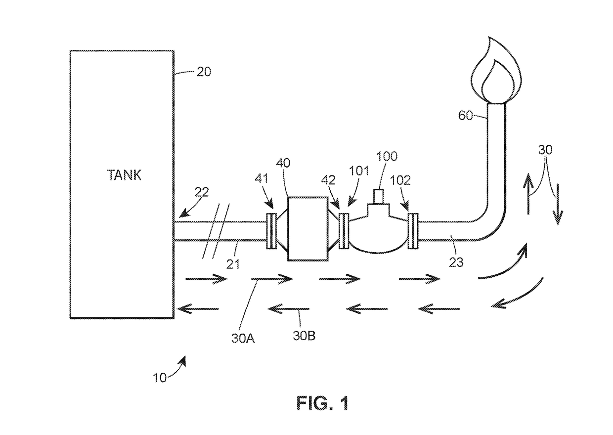
[0019]Referring now to the drawings, and in particular to FIG. 1, a storage system 10 is provided which includes a storage tank 20, a flame arrestor 40, a flare stack 60, and a thermal valve 100. A first conduit 21 extends between the tank 20 and the arrestor 40. A second conduit 23 extends between the thermal valve 100 and the flare stack 60. In the depicted version, the arrestor 40 and the thermal valve 100 are connected directly together, but in other versions, they can be connected by a conduit. The storage tank 20 may include an inlet (not shown) and an outlet 22. A flow path 30 is formed between the storage tank 20 and the flare stack 60 via the first conduit 21, the flame arrestor 40, the thermal valve 100, and the second conduit 23. The flow path 30 allows the fluid to propagate in a first direction 30A extending from the storage tank 20 to the flare stack 60 and in a second, opposite direction 30B extending from the flare stack 60 to the storage tank 20. Generally speaking,...
PUM
 Abstract
Description
Claims
Application Information
 - R&D Engineer
- R&D Manager
- IP Professional
- Industry Leading Data Capabilities
- Powerful AI technology
- Patent DNA Extraction
Browse by: Latest US Patents, China's latest patents, Technical Efficacy Thesaurus, Application Domain, Technology Topic, Popular Technical Reports.
© 2024 PatSnap. All rights reserved.Legal|Privacy policy|Modern Slavery Act Transparency Statement|Sitemap|About US| Contact US: help@patsnap.com