Pipe wrench

a technology of wrenches and clamping rods, which is applied in the field of pipe wrenches, can solve the problems that the link cannot ensure the movement of the two segments is under control, and achieve the effect of quick clamping and dismounting

Inactive Publication Date: 2018-02-06
ZHEJIANG YIYANG TOOL MFG +2
View PDF3 Cites 16 Cited by
  • Summary
  • Abstract
  • Description
  • Claims
  • Application Information

AI Technical Summary

Benefits of technology

[0008]The primary object of the present invention is to provide a pipe wrench which is able to quickly clamp and dismounted from the object by operating the pivotal member.

Problems solved by technology

The link cannot ensure the movement of the two segments is under controlled.

Method used


Image

  • Pipe wrench
  • Pipe wrench
  • Pipe wrench

Examples


Embodiment Construction

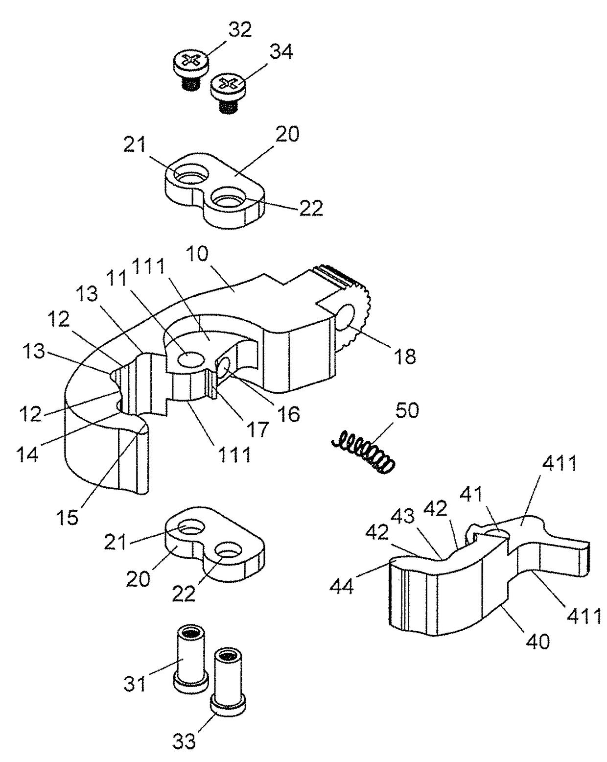
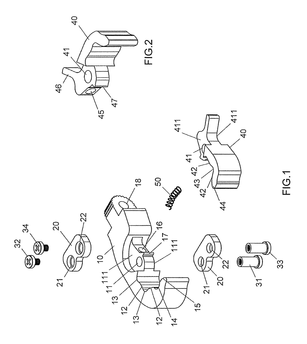
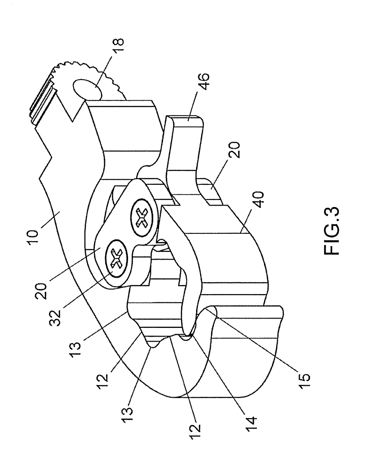
[0019]Referring to FIGS. 1 to 5, the pipe wrench of the present invention comprises a fixed jaw 10 having a first end and a second end which is located opposite to the first end. A pivotal end 18 is formed on the second end of the fixed jaw 10. A first pivotal portion is formed on the inner side of the fixed jaw and located close to the second end of the fixed jaw 10. The thickness of the first pivotal portion a half of the thickness of the fixed jaw 10 so as to define two first recessed areas 111 respectively defined in the top and the bottom of the first pivotal portion. A first hole 11 is defined through the first pivotal portion. Two first recesses 13 and two first driving faces 12 are formed along the inner side of the first jaw 10 and extend from the first end of the first pivotal portion, wherein the first end of the first pivotal portion is located away from the second end of the fixed jaw 10. The two first recesses 13 and the two first driving faces 12 are located alternati...


PUM


Abstract

A pipe wrench includes a fixed jaw with alternatively located first recesses and first driving faces defined in the inner side thereof. A pivotal member is pivotably connected to the fixed jaw and a resilient member is biased between the fixed jaw and the pivotal member. The pivotal member has alternatively located third recesses and second driving faces. A hexagonal space is defined between the first and second driving faces. The end portion of the pivotal member is inserted into a second recess defined in the inner side of the fixed jaw. The object is clamped in the hexagonal space, and the pivotal member can be pivoted away from the fixed jaw. The pipe wrench is able to quickly clamp and dismounted from the object.

Description

BACKGROUND OF THE INVENTION[0001]1. Fields of the Invention[0002]The present invention relates to a pipe wrench, and more particularly, to a pipe wrench with a pivotal clamping member.[0003]2. Descriptions of Related Art[0004]The conventional pipe wrench is disclosed in U.S. Pat. No. 4,967,612, and comprises a pivotal member which has a mounting recess defined in one side thereof, and the pivotal member is pivoted toward the fixed jaw of the wrench so as to clamp the object in the mounting recess. However, after the wrench is rotated an angle, the pivotal member has to be removed from the object, and the wrench is adjusted to another angle, the pivotal member is then pivoted toward the object again to clamp the object.[0005]Another conventional pipe wrench is disclosed in U.S. Pat. No. 6,978,701, and comprises a pivotal member pivotably connected to the body of the wrench so as to be pivoted to clamp the object between the fixed jaw and the pivotal member. The shortcoming is the sam...

Claims


Application Information

Patent Timeline
Patent Type & Authority Patents(United States)
IPC IPC(8): B25B13/50B25B13/46
CPCB25B13/462B25B13/505B25G1/063B25B13/28B25B13/34
Inventor YANG, CHUN-WEIZHANG, ZHE-PINGQIAN, QING-JUN
Owner ZHEJIANG YIYANG TOOL MFG
Why Eureka
Try Eureka