Light emitting element display device
a technology of light-emitting elements and display devices, which is applied in the direction of semiconductor devices, electrical components, electrical apparatus, etc., can solve the problems of display unevenness, degraded display quality, and increased video signal variation, and achieve high display quality
- Summary
- Abstract
- Description
- Claims
- Application Information
AI Technical Summary
Benefits of technology
Problems solved by technology
Method used
Image
Examples
first embodiment
[0102]A configuration of a display device according to the first embodiment of the second aspect in the invention will be described with reference to FIG. 13 to FIG. 18.
Outline of Display Device
[0103]First, an outline of the display device according to the first embodiment will be described with reference to FIG. 13 and FIG. 14. FIG. 13 is a perspective view of the display device in the first embodiment according to the second aspect of the invention. In addition, FIG. 14 is a plan view of the display device in the first embodiment according to the second aspect of the invention.
[0104]As illustrated in FIG. 13 and FIG. 14, the display device in the first embodiment is provided with a light emitting element which is provided in each of a plurality of pixels, a substrate 1100 including a display area 1110 in which pixels 1180 are arranged in a matrix, a counter substrate 1200 facing the substrate 1100, a driver IC 1300 which is provided in an area to which the substrate 1100 is expose...
second embodiment
[0120]Next, a configuration of a display device according to the second embodiment of the second aspect in the invention will be described with reference to FIG. 20 to FIG. 28. Note that, portions which are not specifically mentioned are common in the second embodiment and the first embodiment.
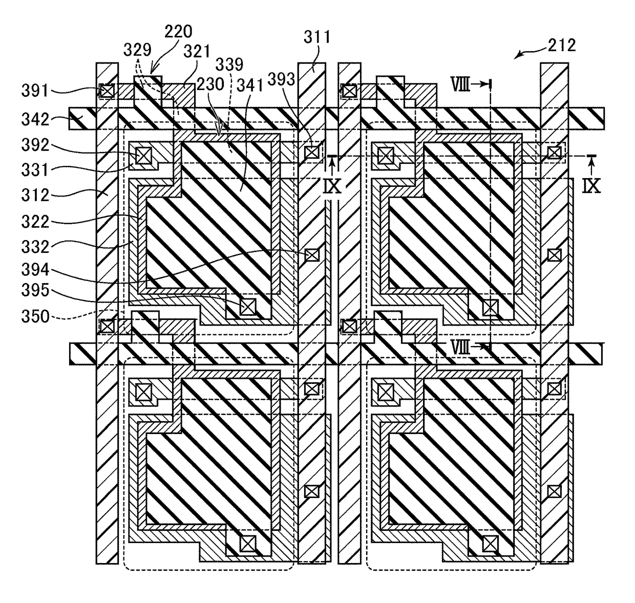
[0121]First, a structure of the display device and a forming method thereof according to the second embodiment will be described with reference to FIG. 20 to FIG. 24. Similar to FIG. 16 to FIG. 19, FIG. 20 to FIG. 24 are perspective plan views when viewed from the display area side of the display device, and illustrate an area 2×2 pixels arranged in the vertical and horizontal directions.
[0122]FIG. 20 illustrates a state in which a LIPS layer 521 and an electrode layer 531 are formed on the same insulating layer. Here, the electrode layer 531 may be obtained by disposing the same material as that of the LIPS layer 521 on the same insulating layer, then performing an ion implantation process th...
modification 1
[0134]Next, Modification 1 of the second embodiment will be described with reference to FIG. 27. In Modification 1, it is found that the electrode layer 532 and the electrode layer 533 are formed to be extended to an area C1 in which the electrode layer 532 and the electrode layer 533 overlap the power line 563 disposed on the right side of the pixel. In this way, when forming an area, in which the power line 563 and the electrode layers 531, 532, and 533 overlap with each other, on the lower side of the power line 563, it is possible to secure a large area in which the capacitor is formed as compared with the second embodiment. Note that, as an application example of Modification 1, it is possible to form an area in which the electrode layers 531, 532, and 533 overlap the signal line 562 on the left side of the pixel without overlapping the power line 563 on the right side of the pixel.
PUM
 Abstract
Description
Claims
Application Information
 - R&D
- Intellectual Property
- Life Sciences
- Materials
- Tech Scout
- Unparalleled Data Quality
- Higher Quality Content
- 60% Fewer Hallucinations
Browse by: Latest US Patents, China's latest patents, Technical Efficacy Thesaurus, Application Domain, Technology Topic, Popular Technical Reports.
© 2025 PatSnap. All rights reserved.Legal|Privacy policy|Modern Slavery Act Transparency Statement|Sitemap|About US| Contact US: help@patsnap.com


