Head and liquid ejecting apparatus

a liquid ejecting apparatus and head technology, applied in printing and other directions, can solve the problems of large amount of ink discharged from the flow path downstream of the filter, difficult or impossible to achieve space saving, and complicated arrangement of branch flow paths and filter chambers, so as to reduce the amount of liquid discharged during cleaning and high-quality ejecting of liquids

Active Publication Date: 2018-02-20
SEIKO EPSON CORP
View PDF13 Cites 4 Cited by
  • Summary
  • Abstract
  • Description
  • Claims
  • Application Information

AI Technical Summary

Benefits of technology

[0011]An advantage of some aspects of the invention is that a head and a liquid ejecting apparatus that are capable of realizing high-quality ejection of liquid while making the configuration of branched flow paths as compact as possible are provided. Another advantage of some aspects of the invention is that a head and a liquid ejecting apparatus capable of reducing the amount of liquid discharged in the cleaning operation are provided.
[0013]In this exemplary embodiment, an upstream portion to which the liquid supplied from the liquid supply unit flows connects to an intermediate portion of the horizontal flow path and the path is branched to two opposite sides in the horizontal flow path, equal and smooth branching can be achieved and, furthermore, the degree of freedom in laying out the branch flow paths can be improved and space saving can be facilitated. This also makes it possible to supply the liquid corresponding to the symmetrical arrangement of the nozzle rows and also to improve the ease in discharging gas bubbles during cleaning and reduce the amount of the liquid discharged for cleaning. Furthermore, even in a construction in which a plurality of liquid flow paths are each branched corresponding to the symmetrical arrangement of the nozzle rows, the pressure of the liquids supplied to the nozzle rows can be inhibited from varying among the nozzle rows. Due to this, a head capable of performing high-quality ejection of liquids can be provided.
[0015]This eliminates the stagnation of the liquid caused by the branching, so that space-saving and uniform branching can be achieved.
[0017]This eliminates unnecessary flow paths and allows further space saving.
[0021]This aspect of the invention provides a liquid ejecting apparatus that allows the space saving of flow paths and that is capable of realizing high-quality ejection of liquids and reducing the amount of the liquids discharged during cleaning.

Problems solved by technology

However, in the flow path member provided with branched flow paths for various color inks, particularly in a construction in which the nozzle rows are symmetrically disposed separately for each color ink, the arrangement of the branch flow paths and filter chambers is complicated so that it is difficult or impossible to achieve space saving.
Therefore, in the cleaning operation, the amount of ink discharged from the flow paths downstream of the filters is large.

Method used


Image

  • Head and liquid ejecting apparatus
  • Head and liquid ejecting apparatus
  • Head and liquid ejecting apparatus

Examples


exemplary embodiment 1

[0037]An exemplary embodiment of the invention will be described in detail below. This exemplary embodiment of the invention will be described in conjunction with an ink jet type recording head (hereinafter, simply referred to as head) that ejects ink as an example of a permanent head.

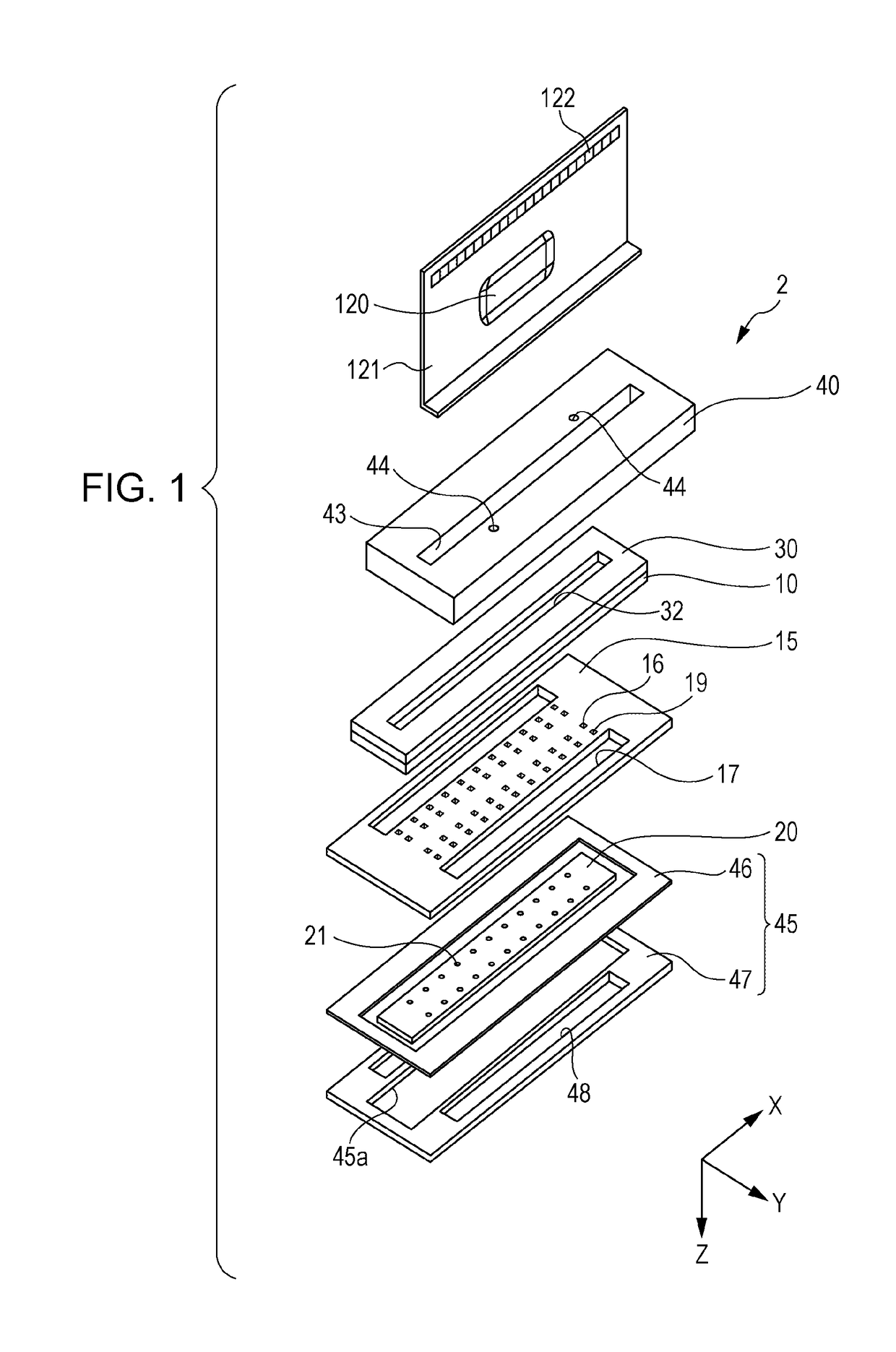
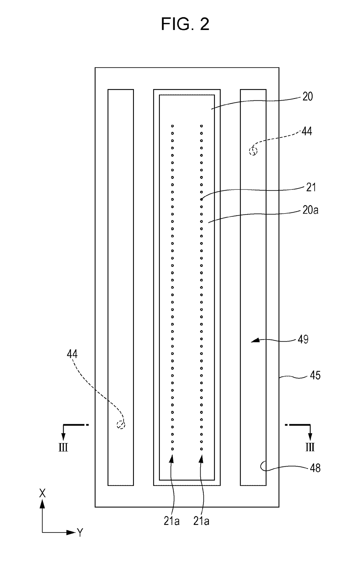
[0038]First, an example of a head body provided in a head according to this exemplary embodiment will be described. FIG. 1 is an exploded perspective view of a head body. FIG. 2 is a plan view of the head body. FIG. 3 is a sectional view of the head body taken on line III-III in FIG. 2.

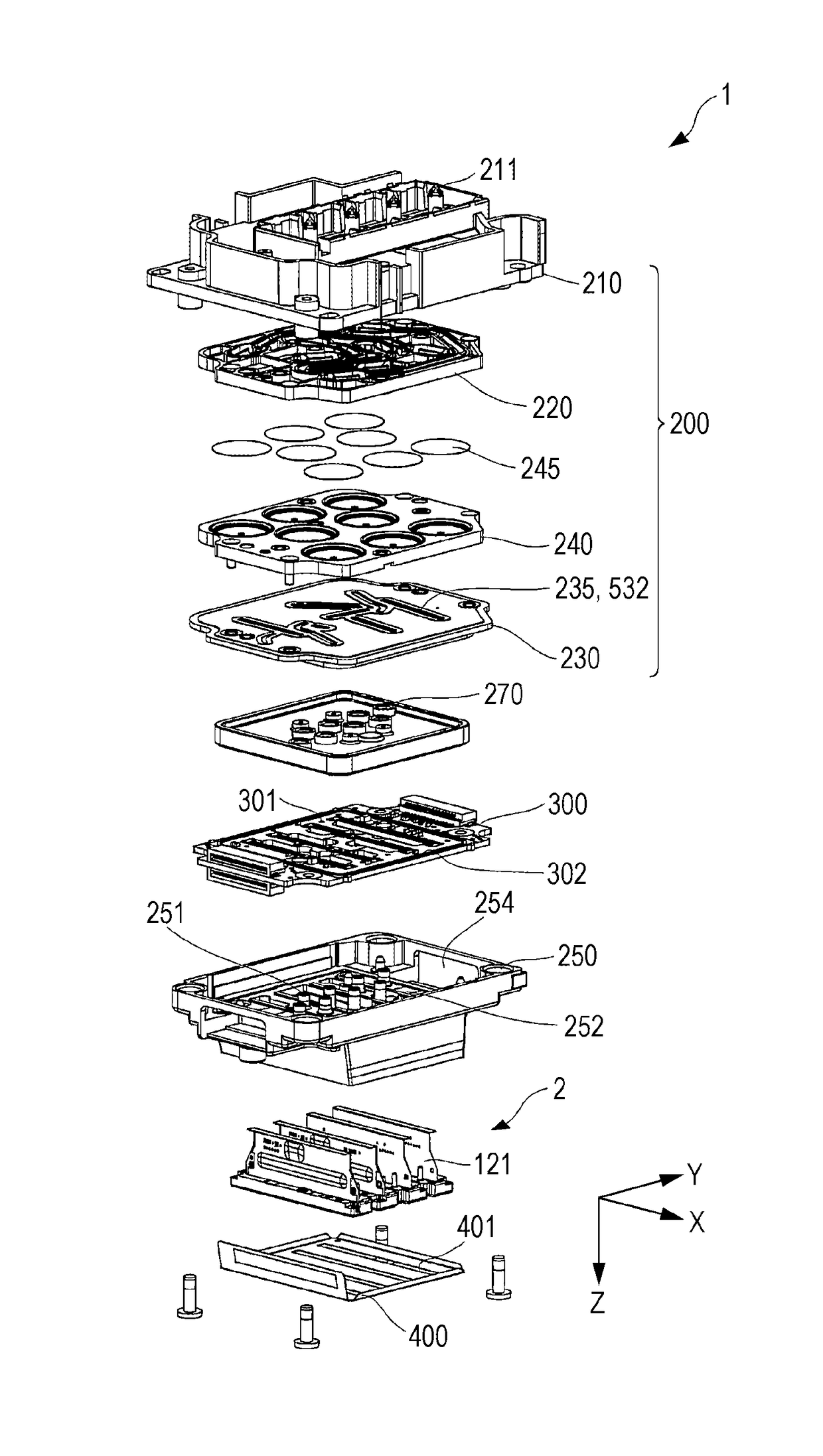
[0039]A head body 2 includes a plurality of members such as a flow path formation substrate 10, a communication plate 15, a nozzle plate 20, a protective substrate 30, a compliance substrate 45, a case member 40, and a wiring board 121.

[0040]The flow path formation substrate 10 may be made of a metal, such as stainless steel or nickel (Ni), a ceramic material represented by zirconium oxide (ZrO2) or aluminum oxide (Al2O3...

exemplary embodiment 2

[0130]The head 1 described above in conjunction with Exemplary Embodiment 1 is mounted in an ink jet type recording apparatus I. FIG. 14 is a schematic diagram showing an ink jet type recording apparatus as an example of a liquid ejecting apparatus.

[0131]In an ink jet type recording apparatus I shown in FIG. 14, the head 1 is provided with detachably attached ink cartridges 110, which are a liquid supply unit. A carriage 3 on which the head 1 is mounted is provided on a carriage shaft 5 attached to the apparatus main body 4. The carriage 3 is movable along an axis direction of the carriage shaft 5.

[0132]As drive force from a driving motor 6 is transmitted to the carriage 3 via a plurality of gears (not graphically shown) and a timing belt 7 so that the carriage 3 on which the head 1 is mounted moves along the carriage shaft 5. On the other hand, the apparatus main body 4 is provided with a transport roller 8 as a transport unit, so that a recording sheet S that is a recording medium...


PUM


Abstract

Nozzle rows that discharge the same liquids are disposed at locations symmetrical about a reference line. The flow path member includes a first flow path member, a second flow path member joined to the first flow path member, a filter retainer member that is joined to the second flow path member and that holds filters, a third flow path member that is joined to the filter retainer member. The liquid flow path includes first horizontal flow paths that are provided between the first flow path member and the second flow path member and that divide the liquid supplied from the liquid supply unit and buffer chambers provided on the first horizontal flow paths. Between the second flow path member and the filter retainer member, filter chambers are provided in regions that face the buffer chambers. The buffer chambers communicate with central portions of the filter chambers.

Description

BACKGROUND1. Technical Field[0001]The present invention relates to a head and a liquid ejecting apparatus and, more particularly, to an ink jet type recording head and an ink jet type recording apparatus that ejects ink as a liquid.2. Related Art[0002]A piezo ink jet system is an on-demand type ink jet print system that discharges droplets of ink by deforming piezo elements through application of voltage (JIS Z8123-1:2013).[0003]A permanent head (hereinafter, simply termed head) is a mechanical or electrical component of a printer main body which continually or intermittently produces liquid droplets of ink (JIS Z8123-1:2013).[0004]A head for use in the piezo ink jet system includes a flow path formation substrate provided with a pressure generation chamber that communicates with a nozzle that ejects a liquid droplet, a piezo element provided on the side of one surface of the flow path formation substrate, and a drive circuit substrate joined to a piezo element side of the flow path...

Claims


Application Information

Patent Timeline
Patent Type & Authority Patents(United States)
IPC IPC(8): B41J2/14B41J2/17B41J2/045B41J2/175
CPCB41J2/14201B41J2/04581B41J2/1433B41J2/17563B41J2/1707B41J2002/14306B41J2/175B41J2/14233B41J2002/14362B41J2002/14419
Inventor MIYAJIMA, HIROKI
Owner SEIKO EPSON CORP
Why Eureka
Try Eureka