System and method for generating high power pulses

a high-power pulse and pulse technology, applied in the field of generating high-power rf pulses and/or high-power microwave pulses, can solve the problems of inability to use the energy stored in the dc component and the very low frequency components of the output pulse of the system, and the radiating efficiency of the system is very low, so as to increase the conversion efficiency of direct current (dc) to radio frequency (rf)

Inactive Publication Date: 2018-02-20
BAE SYST INFORMATION & ELECTRONICS SYST INTERGRATION INC
View PDF7 Cites 4 Cited by
  • Summary
  • Abstract
  • Description
  • Claims
  • Application Information

AI Technical Summary

Problems solved by technology

For example, the energy stored in the DC component and very low frequency components of the resulting output pulse of the system cannot be used (i.e. cannot be radiated).
Since the portion of energy stored in these components substantially exceeds the energy stored in the RF or microwave components the radiating efficiency of the system is very low.
Further, systems that utilize a Blumlein generator are typically heavy in weight which hinders practical application of the systems.
Still further, the pulse repetition rate is limited by thermal and cooling issues as well as the charge rate available into the high voltage video pulse generator.
One disadvantage of using spark gap switches is that spark gap switches require periodic maintenance and replacement.
Another disadvantage is that high voltage Blumlein generators that utilize spark gap switches cannot be recharged in a short period of time (e.g. within a subnanosecond range).
This limits the maximal repetition rate and the output energy of the system.
In other words, jitter, amongst other things, limits the number of devices which can be synchronized for coherent output power which typically limits the output RF and / or microwave power of the system.

Method used


Image

  • System and method for generating high power pulses
  • System and method for generating high power pulses
  • System and method for generating high power pulses

Examples


Embodiment Construction

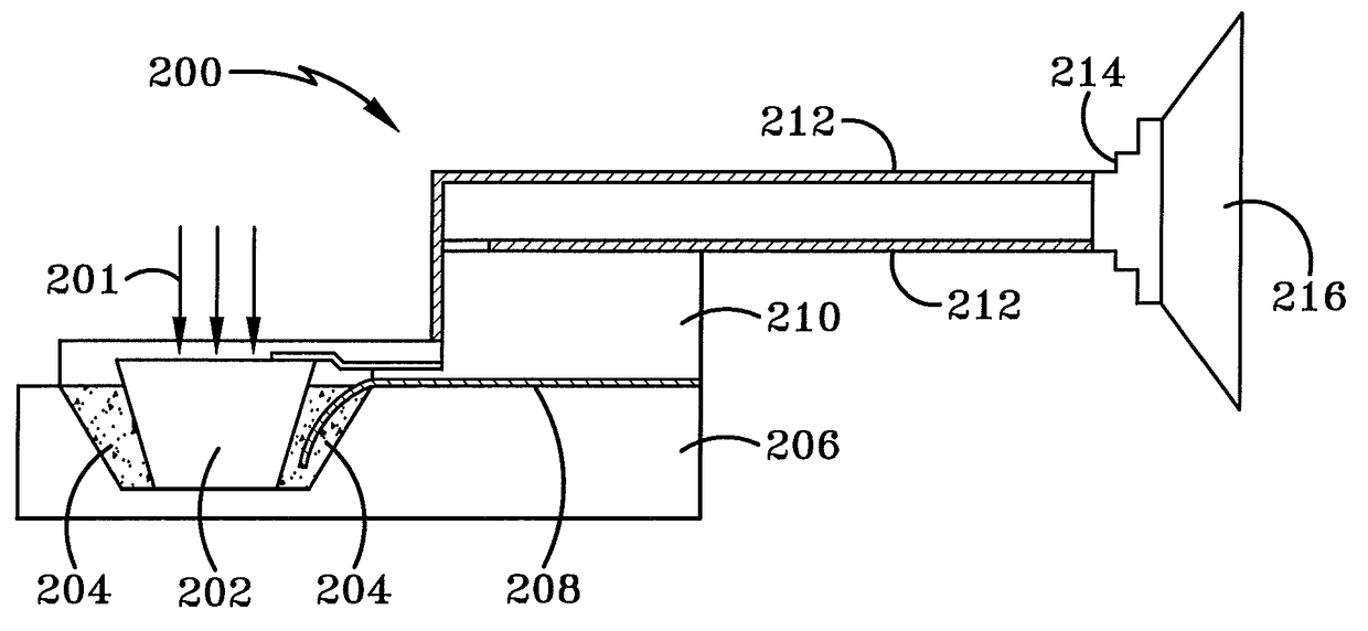
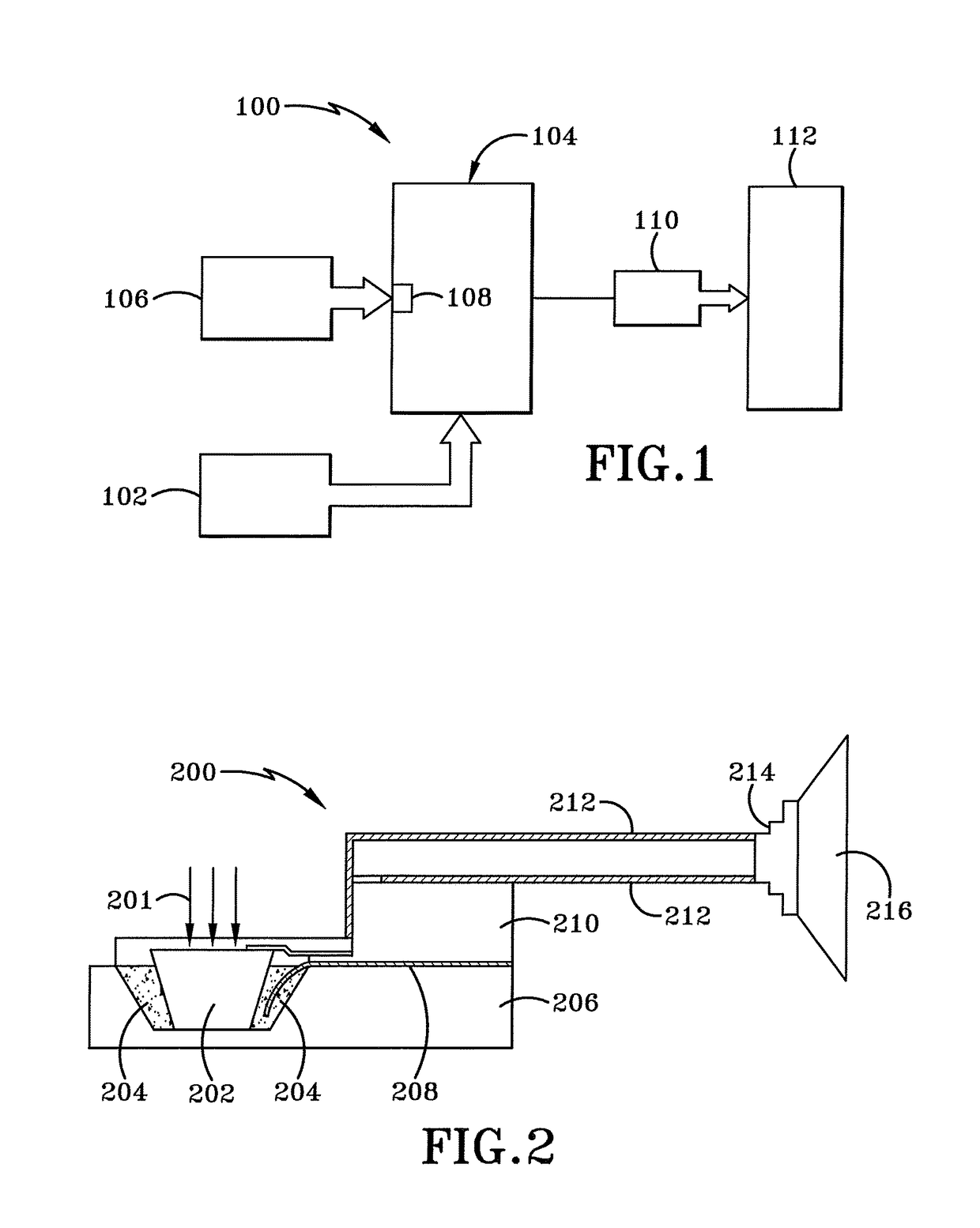
[0023]As depicted in FIG. 1, a system for generating high power RF and / or microwave pulses is broadly depicted as 100. System 100 may include a power supply 102, at least one high power pulse generator 104, a laser 106, at least one optically activated photoconductive semiconductor switch (PCSS) 108, at least one modulator unit 110 and at least one antenna 112.

[0024]With continued reference to FIG. 1, power supply 102 includes an output which is electrically connected to the at least one high power pulse generator 104 through an input of the high power pulse generator 104. The at least one high power pulse generator 104 includes at least one input and at least one output. The high power pulse generator 104 is electrically coupled to the at least one PCSS 108. The at least one PCSS 108 is positioned to receive a pulse from the laser 106. The at least one modulator unit 110 includes at least one input and at least one output. The at least one modulator unit 110 is electrically connect...


PUM


Abstract

A system and method for generating high power pulses including a photoconductive semiconductor switch (PCSS), a laser for triggering the PCSS and a bipolar pulse generator coupled to the PCSS. The bipolar pulse generator is activated when the PCSS is triggered. A bipolar pulse is generated by the activated bipolar pulse generator. A modulator unit modulates the bipolar pulse to create a modulated bipolar pulse. The modulator unit is a nonlinear transmission line (NLTL).

Description

BACKGROUNDTechnical Field[0001]The present disclosure relates generally to the field of generating radio frequency (RF) and / or microwave signals. More particularly, the present disclosure relates to generating high power RF pulses and / or high power microwave pulses. Specifically, the present disclosure relates to generating high power RF and / or microwave pulses based at least partially on utilizing a bipolar signal driver, utilizing optically-activated switches and specifying specific pulse profiles.Background Information[0002]Generally, high power RF and / or microwave pulse generators based on non-linear transmission lines (NLTLs) typically use high voltage unipolar pulses as pump pulse generators (e.g. video or rectangular pulse generators). Typically, these types of systems utilize a high voltage Blumlein generator as the video pulse generator where the Blumlein generator is typically activated by spark gap switches or thyratrons. A resulting output pulse of the system consists of...

Claims


Application Information

Patent Timeline
Patent Type & Authority Patents(United States)
IPC IPC(8): H04L27/36H04B3/50
CPCH04L27/36H04B3/50
Inventor LONDON, SIMON Y.KOZYREV, ALEXANDER B.CLARK, STUART E.
Owner BAE SYST INFORMATION & ELECTRONICS SYST INTERGRATION INC
Why Eureka
Try Eureka