Rotating lock latch bolt and locks having the rotating lock latch bolts

a technology of latch bolts and rotating locks, which is applied in the field of rotating lock latch bolts, and can solve the problems of affecting the operation of the locking mechanism

Active Publication Date: 2018-02-27
NANJING EASTHOUSE ELECTRIC CO LTD
View PDF14 Cites 5 Cited by
  • Summary
  • Abstract
  • Description
  • Claims
  • Application Information

AI Technical Summary

Benefits of technology

[0004]In order to prevent content in a safe from being unauthorized accessed, a lock is usually used. The locking and unlocking of the lock are controlled by a locking mechanism either electrically or mechanically. Currently, the locking mechanism includes at least a swinging lock latch or a sliding lock latch to keep a lock locked or unlocked. The strength and stability of the lock depend on the dimension and strength of the lock latch, the dimension and strength of the lock latch support, and travelling distance of the movement of the lock latch. When the lock latch and the lock latch support are not big enough, or not strong enough, and when travelling distance of the movement of the lock latch is not long enough, the locking mechanism may not have sufficient strength to prevent breakage of the lock. Certain design of the locks may be easily broken by exerting a moderate force on the lock latch and the locking mechanism may fail. Furthermore, certain locking mechanism may be easily unlocked by applying impacting force, especially along a direction of a linear motion trajectory of a key-drawn locking mechanism, the key-drawn locking mechanism may produce instant movement causing instant unlocking by moving out of the motion trajectory of the locking tab. It is desirable to have a mechanism to prevent the lock latch from moving.
[0004]In order to prevent content in a safe from being unauthorized accessed, a lock is usually used. The locking and unlocking of the lock are controlled by a locking mechanism either electrically or mechanically. Currently, the locking mechanism includes at least a swinging lock latch or a sliding lock latch to keep a lock locked or unlocked. The strength and stability of the lock depend on the dimension and strength of the lock latch, the dimension and strength of the lock latch support, and travelling distance of the movement of the lock latch. When the lock latch and the lock latch support are not big enough, or not strong enough, and when travelling distance of the movement of the lock latch is not long enough, the locking mechanism may not have sufficient strength to prevent breakage of the lock. Certain design of the locks may be easily broken by exerting a moderate force on the lock latch and the locking mechanism may fail. Furthermore, certain locking mechanism may be easily unlocked by applying impacting force, especially along a direction of a linear motion trajectory of a key-drawn locking mechanism, the key-drawn locking mechanism may produce instant movement causing instant unlocking by moving out of the motion trajectory of the locking tab. It is desirable to have a mechanism to prevent the lock latch from moving.

Problems solved by technology

When the lock latch and the lock latch support are not big enough, or not strong enough, and when travelling distance of the movement of the lock latch is not long enough, the locking mechanism may not have sufficient strength to prevent breakage of the lock.
Certain design of the locks may be easily broken by exerting a moderate force on the lock latch and the locking mechanism may fail.
Therefore, heretofore unaddressed needs exist in the art to address the aforementioned deficiencies and inadequacies.

Method used


Image

  • Rotating lock latch bolt and locks having the rotating lock latch bolts
  • Rotating lock latch bolt and locks having the rotating lock latch bolts
  • Rotating lock latch bolt and locks having the rotating lock latch bolts

Examples


Embodiment Construction

[0028]The present invention will now be described more fully hereinafter with reference to the accompanying drawings, in which exemplary embodiments of the invention are shown. This invention may, however, be embodied in many different forms and should not be construed as limited to the embodiments set forth herein. Rather, these embodiments are provided so that this disclosure will be thorough and complete, and will fully convey the scope of the invention to those skilled in the art.

[0029]The terms used in this specification generally have their ordinary meanings in the art, within the context of the disclosure, and in the specific context where each term is used. Certain terms that are used to describe the disclosure are discussed below, or elsewhere in the specification, to provide additional guidance to the practitioner regarding the description of the disclosure. The use of examples anywhere in this specification, including examples of any terms discussed herein, is illustrativ...


PUM


Abstract

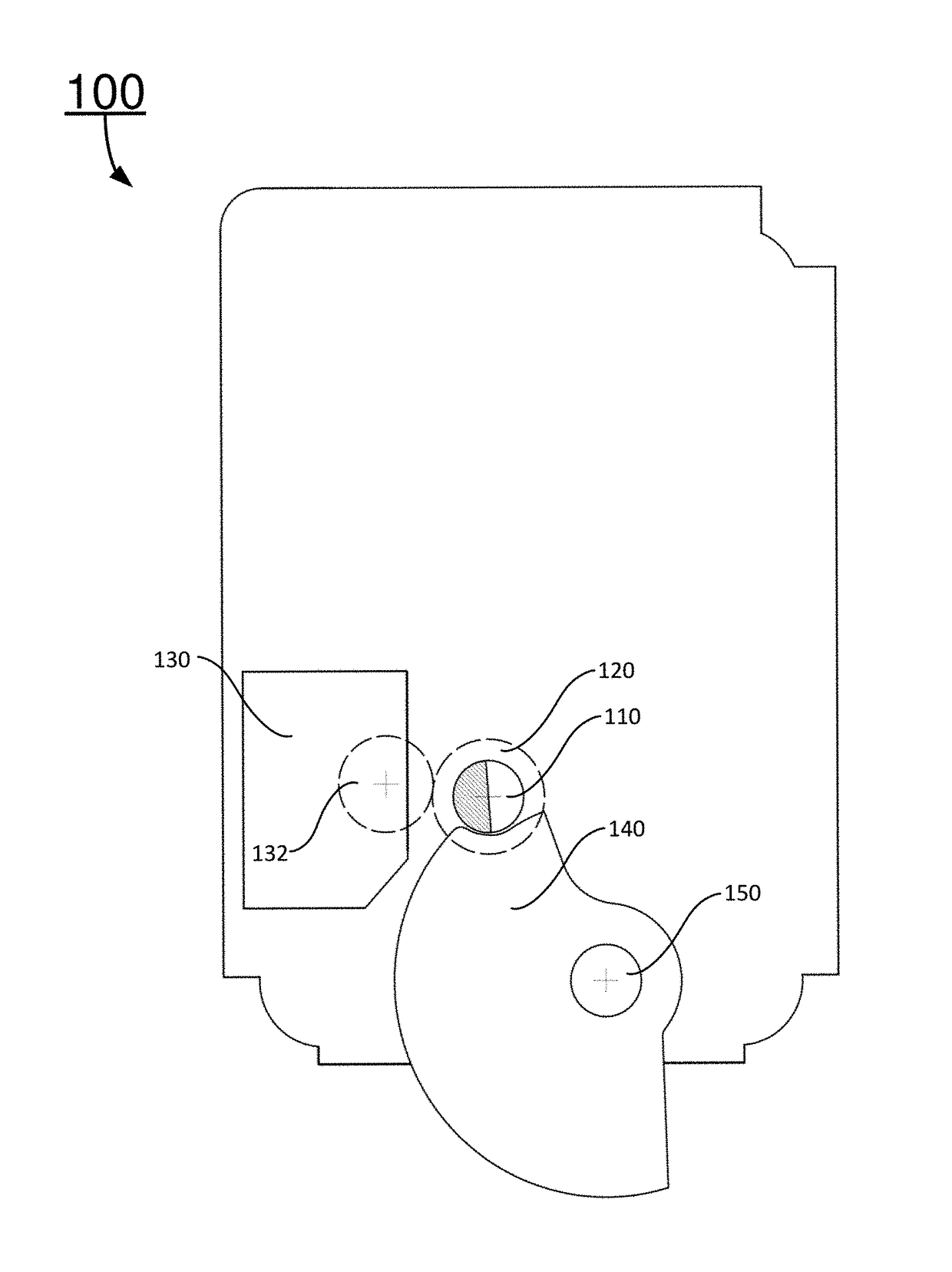
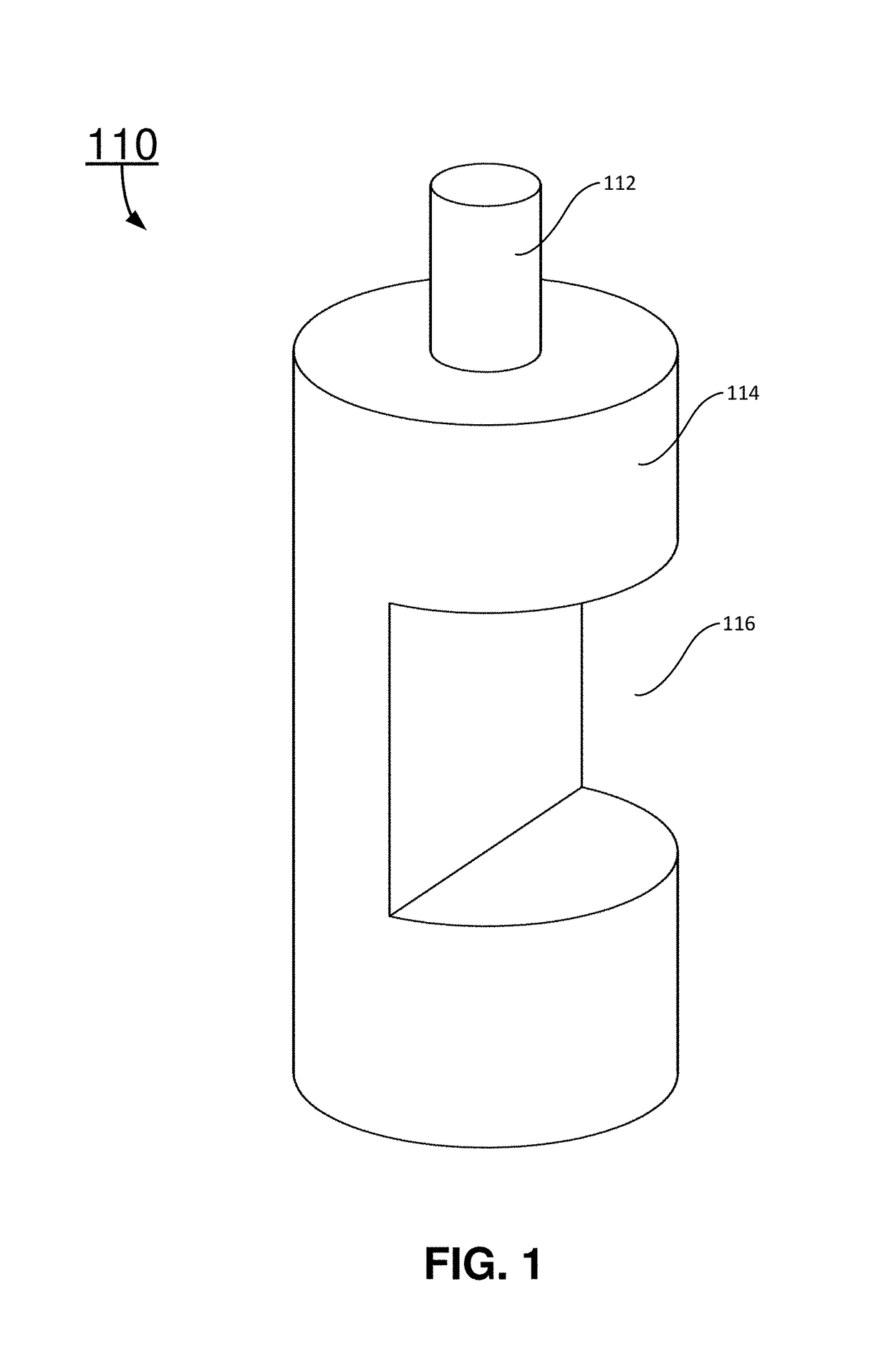
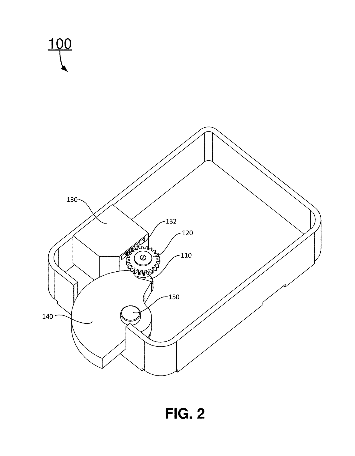
The present disclosure relates to a rotating lock latch bolt and a lock having rotating lock latch bolt. In certain embodiments, rotating lock latch bolt may include a first cylindrical body and a second cylindrical body connected co-axially below the first cylindrical body. The lock may include a lock latch, a lock latch control mechanism, a rotating lock latch bolt, and a rotating lock latch bolt control mechanism. Lock latch control mechanism may be configured to drive lock latch to a first position to lock the lock, and to a second position to unlock the lock. The rotating lock latch bolt may be configured to bolt the lock latch to prevent the lock latch from moving when the lock latch is in the first position. The rotating lock latch bolt control mechanism may be configured to rotate the rotating lock latch bolt to bolt and release the lock latch.

Description

CROSS-REFERENCE TO RELATED APPLICATION[0001]This application is a continuation of a PCT / CN2014 / 090931, filed with the State Intellectual Property Office of China on Nov. 12, 2014, entitled “Rotating Lock Latch Bolt and Locks Having the Rotating Lock Latch Bolts”, by Jianping SUN, and Hao MIN, which claims priority of Chinese Patent Application No. 201410175836.5, filed on Apr. 29, 2014, entitled “Rotating Lock Latch Bolt and Locks Having the Rotating Lock Latch Bolts” by Jianping SUN, and Hao MIN, the disclosures of which are incorporated herein by reference in their entirety.[0002]Some references, if any, which may include patents, patent applications and various publications, may be cited and discussed in the description of this invention. The citation and / or discussion of such references, if any, is provided merely to clarify the description of the present invention and is not an admission that any such reference is “prior art” to the invention described herein. All references li...

Claims


Application Information

Patent Timeline
Patent Type & Authority Patents(United States)
IPC IPC(8): E05B17/20E05B65/00E05B47/06E05B49/00
CPCE05B17/2034E05B65/0075E05B49/00E05B47/0607
Inventor MIN, HAOSUN, JIANPING
Owner NANJING EASTHOUSE ELECTRIC CO LTD
Why Eureka
Try Eureka