Coupling member for scaffoldings

a technology of coupling member and scaffolding, which is applied in the field of coupling member, can solve the problems of limited strength and robustness of the pivoting clamping member, limiting the dimension of the pivoting lower clamping member, etc., and achieves compact and strong design of the second clamping part, simple and reliable, and more reliable function

Active Publication Date: 2018-03-13
PLUSEIGHT TECH AB
View PDF25 Cites 0 Cited by
  • Summary
  • Abstract
  • Description
  • Claims
  • Application Information

AI Technical Summary

Benefits of technology

[0009]In the prior art design of WO 02 / 22989, the pivoting lower clamping member is arranged in the main body of the coupling device, thereby limiting the dimension of the pivoting lower clamping member, because the shape and form of the lower clamping member is directly dependent on the space available inside the hook-shaped body. This limitation in space results in a limited strength and robustness of the pivoting clamping member. The inventive first clamping part, with its externally arranged and transversally spaced apart side parts, provides improved strength and robustness of the pivoting clamping part itself, due to reduced limitation in dimension and type of material used for the first clamping part, thereby leading to improved possibilities of robust design and high safety. Furthermore, the increased width of interaction between the first clamping part and the upright due to the increased width of the first clamping part itself by means of the large transversal distance between the side portions results in a more rigid coupling between coupling member and the upright, in particular an increased torsional rigidity around the longitudinal axis of the coupling member.
[0022]Further, said wedge-shaped locking part may be arranged partly between said two hook-shaped side parts of said hook-shaped coupling part, and said wedge-shaped locking part may be arranged partly within said cavity of said first clamping part. This arrangement has the advantage of providing protection of the wedge-shaped locking part from external undesired operation thereof. It is important that the locking arrangement only enters the release position upon operation of the user, and never due to unforeseen interaction with other parts of the scaffolding or persons using it. Moreover, the inventive arrangement of the wedge-shaped locking part results in increased symmetry of the coupling member, and thus improved reliability.

Problems solved by technology

In the prior art design of WO 02 / 22989, the pivoting lower clamping member is arranged in the main body of the coupling device, thereby limiting the dimension of the pivoting lower clamping member, because the shape and form of the lower clamping member is directly dependent on the space available inside the hook-shaped body.
This limitation in space results in a limited strength and robustness of the pivoting clamping member.

Method used


Image

  • Coupling member for scaffoldings
  • Coupling member for scaffoldings
  • Coupling member for scaffoldings

Examples


Embodiment Construction

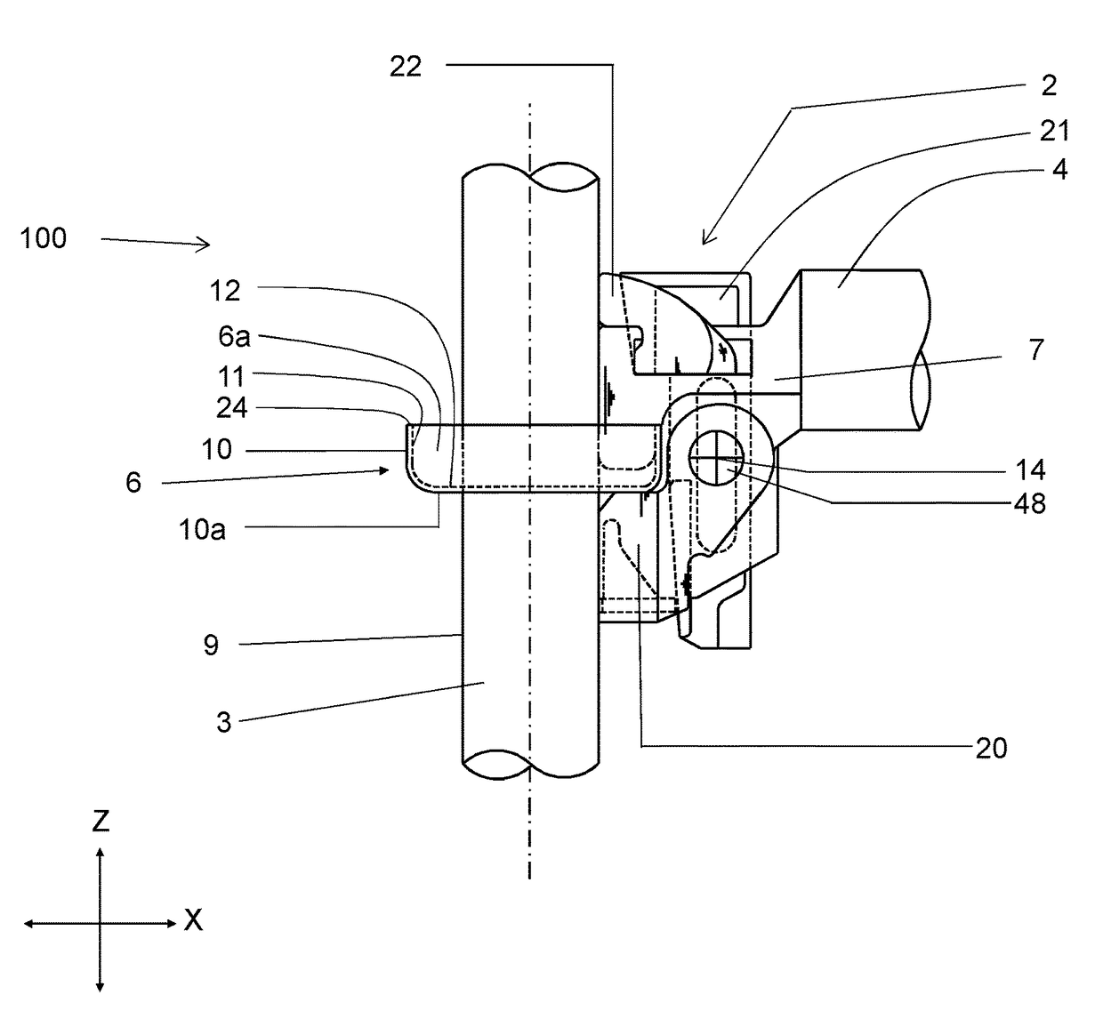
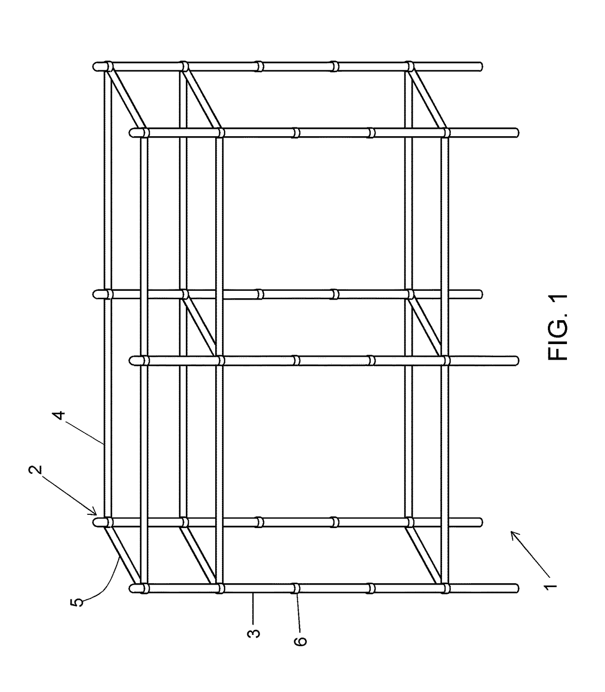
[0036]FIG. 1 shows an example of a scaffolding 1 that is equipped with coupling members 2 which can be of the type as described by the present invention. The scaffolding 1 comprises a number of uprights 3 also known as standards which are essentially vertically oriented tubes and a number of scaffolding members 4, 5 which are essentially horizontally oriented tubes and are also known as ledgers. Further, the uprights 3 and the scaffolding members 4, 5 are coupled with each other by the coupling member 2 of the present invention to form the scaffolding 1. The uprights 3 rest at their lower end on a surface which can be the ground, a sidewalk, a floor or the like. The scaffolding elements 4, 5 are at their both ends coupled to the uprights 3 by means of the coupling members 2. The coupling member 2 according to the invention is an extremely rigid coupling and is capable of providing a scaffold that stands alone without external support. However, in traditional applications, when the s...


PUM


Abstract

A coupling member includes a hook-shaped coupling part arranged to be hooked into a gripping part of an upright and a locking arrangement switchable between a locking position and a release position. Further, the locking arrangement includes a pivotally attached first clamping part and a wedge-shaped locking part, which is slidable between a locking position and a release position. The wedge-shaped locking part is arranged to push the first clamping part towards the upright and the gripping part by means of wedge action. Moreover, the first clamping part comprises two transversally spaced apart side parts which jointly define a cavity there between. The first clamping part is arranged externally on the hook-shaped coupling part, and is arranged partly within the cavity. Further, each of the side parts includes fastening means for pivotal attachment of the first clamping part to the hook-shaped coupling part.

Description

CROSS REFERENCE TO RELATED APPLICATIONS[0001]This application is a U.S. National Phase patent application of PCT / SE2012 / 051033, filed on Sep. 27, 2012, which claims priority to Swedish Patent Application No. 1150930-4, filed on Oct. 10, 2011, each of which is hereby incorporated by reference in the present disclosure in its entirety.TECHNICAL FIELD[0002]The present invention pertains to a coupling member for coupling together scaffolding elements and uprights in a scaffold structure.BACKGROUND ART[0003]Scaffoldings are temporary structures built around construction sites / buildings or the like to support workers and materials. Scaffoldings in early days were built of wood and bamboo and pieces of rope were used to secure the components. In present day, scaffoldings are made up of iron pipes / tubes and mechanical coupling members are used to secure these pipes / tubes. Several such coupling members in numerous configurations are available in the market to choose from. Further, there are ...

Claims


Application Information

Patent Timeline
Patent Type & Authority Patents(United States)
IPC IPC(8): E04G7/00E04G7/12E04G7/32E04G7/34E04G7/30
CPCE04G7/12E04G7/307E04G7/32E04G7/34Y10T403/42F16B2200/67E04G7/00E04G7/30
Inventor WALLTHER, HARRY
Owner PLUSEIGHT TECH AB
Why Eureka
Try Eureka