
Wind turbine

Inactive Publication Date: 2012-07-26
COMET
View PDF39 Cites 1 Cited by
  • Summary
  • Abstract
  • Description
  • Claims
  • Application Information

AI Technical Summary

Benefits of technology

[0022]The aim of the present invention is to provide a wind turbine that satisfies these requirements, is simple in shape, exhibits limited overall dimensions, and produces a high fluid-dynamic yield.
[0024]The dependent claims describe characteristics that improve the performance of the invention.

Problems solved by technology

Vertical-axis machines are of limited dimensions and are more suited to urban wind patterns which are normally turbulent, extremely variable in direction and strength, and consequently badly suited to horizontal axis turbines.
Generators of known type exhibit a number of disadvantages which to date have not been successfully resolved.
A first disadvantage is aesthetic, since in order to provide an acceptable level of power wind turbines must be arranged in arrays or “farms” comprising a considerable number of turbines.
Wind farms must be positioned in windy areas and unavoidably compromise landscape which is often of considerable environmental relevance, and their construction is understandably opposed by local authorities.
Environmental impact is worsened by the fact that the air currents required to turn the fluid-dynamic means of the turbines are generally found at a significant height above ground, making it necessary to construct turbines of a considerable height.
A second disadvantage, technical in nature, is the limited yield of known fluid-dynamic means which are efficient only if the wind speed is above approximately 6 m / sec., a velocity that is rarely encountered in proximity to urban areas, and consequently any generated electricity is subject to significant transport costs.

Method used


Image

  • Wind turbine
  • Wind turbine
  • Wind turbine

Examples


Embodiment Construction

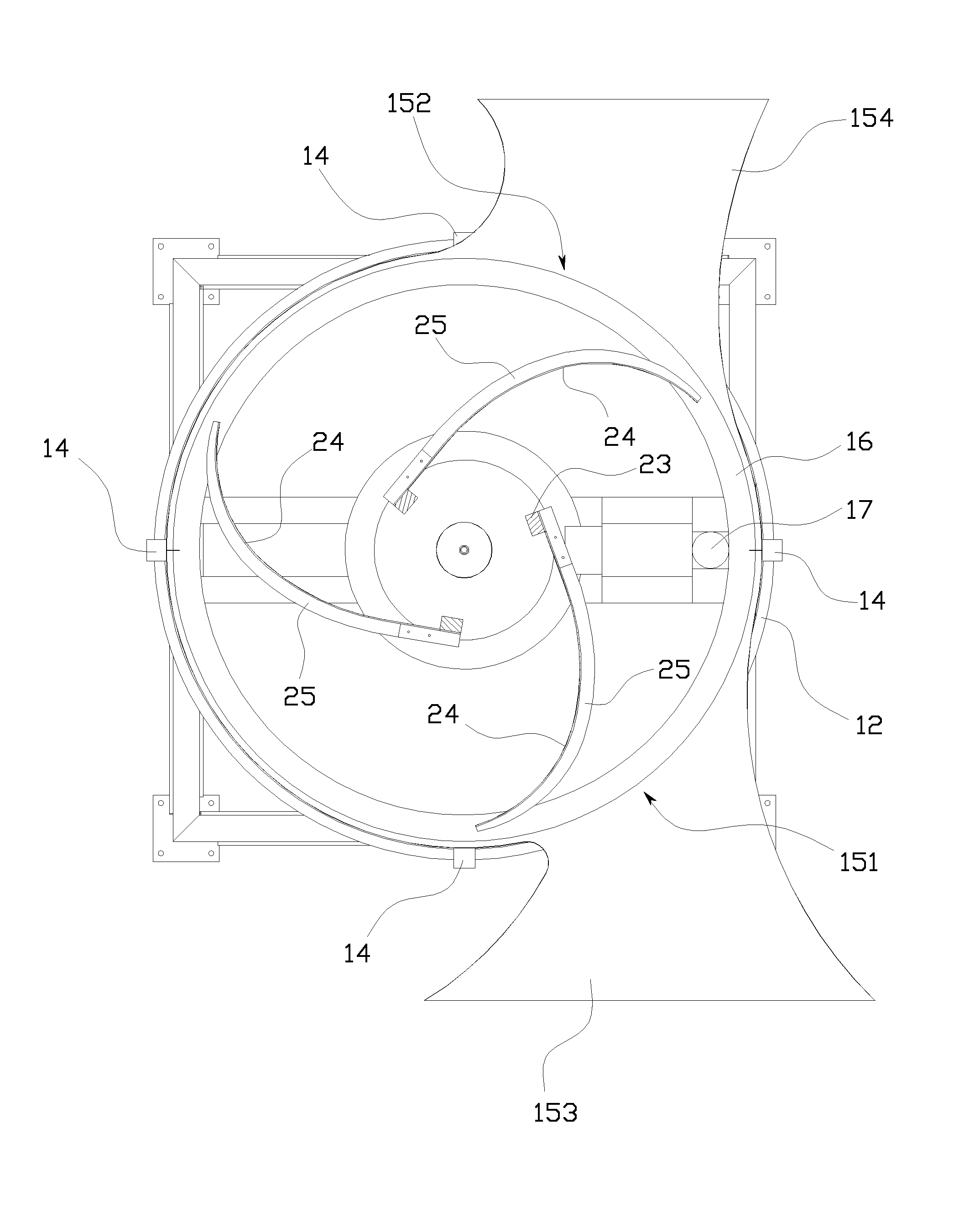
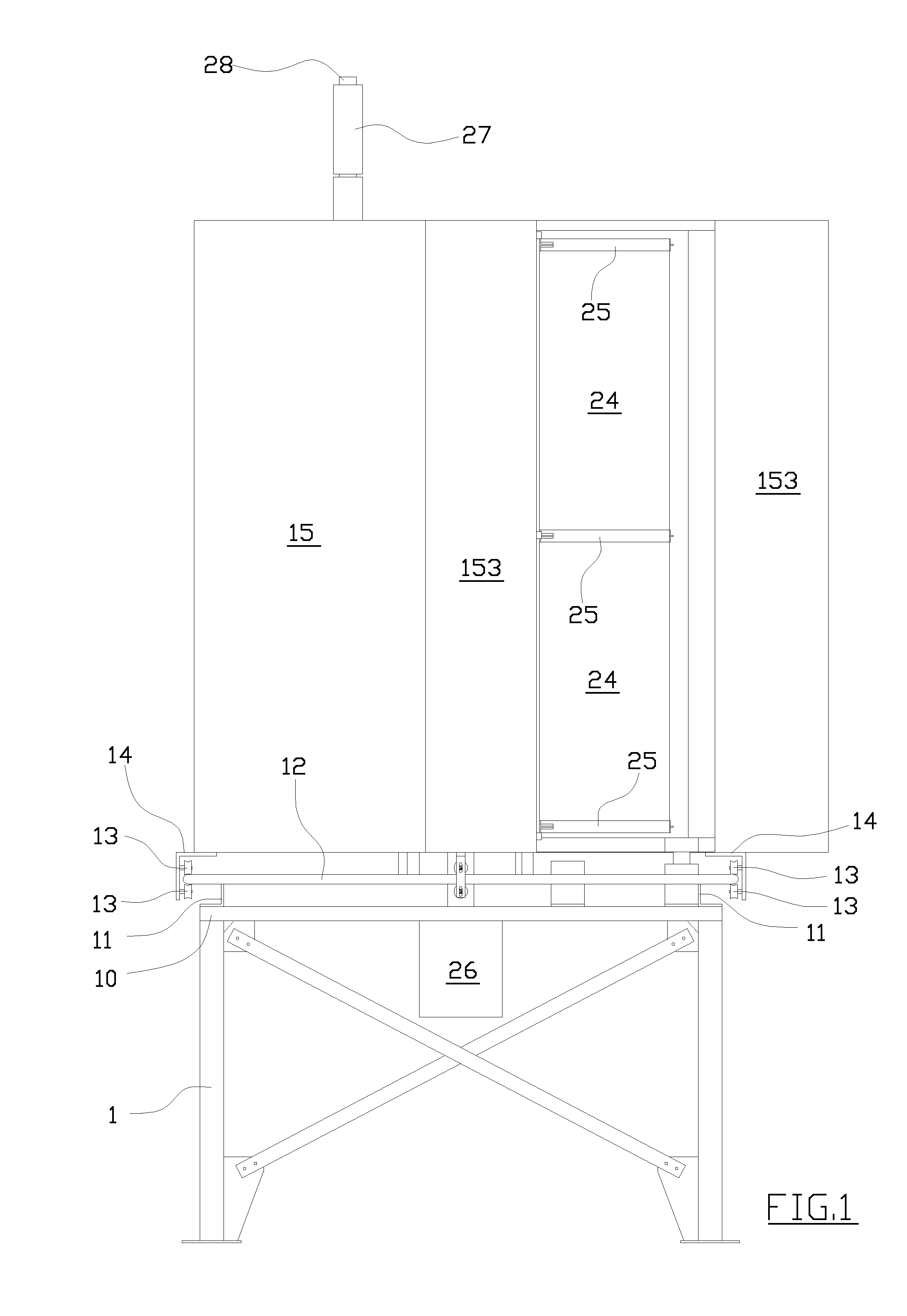
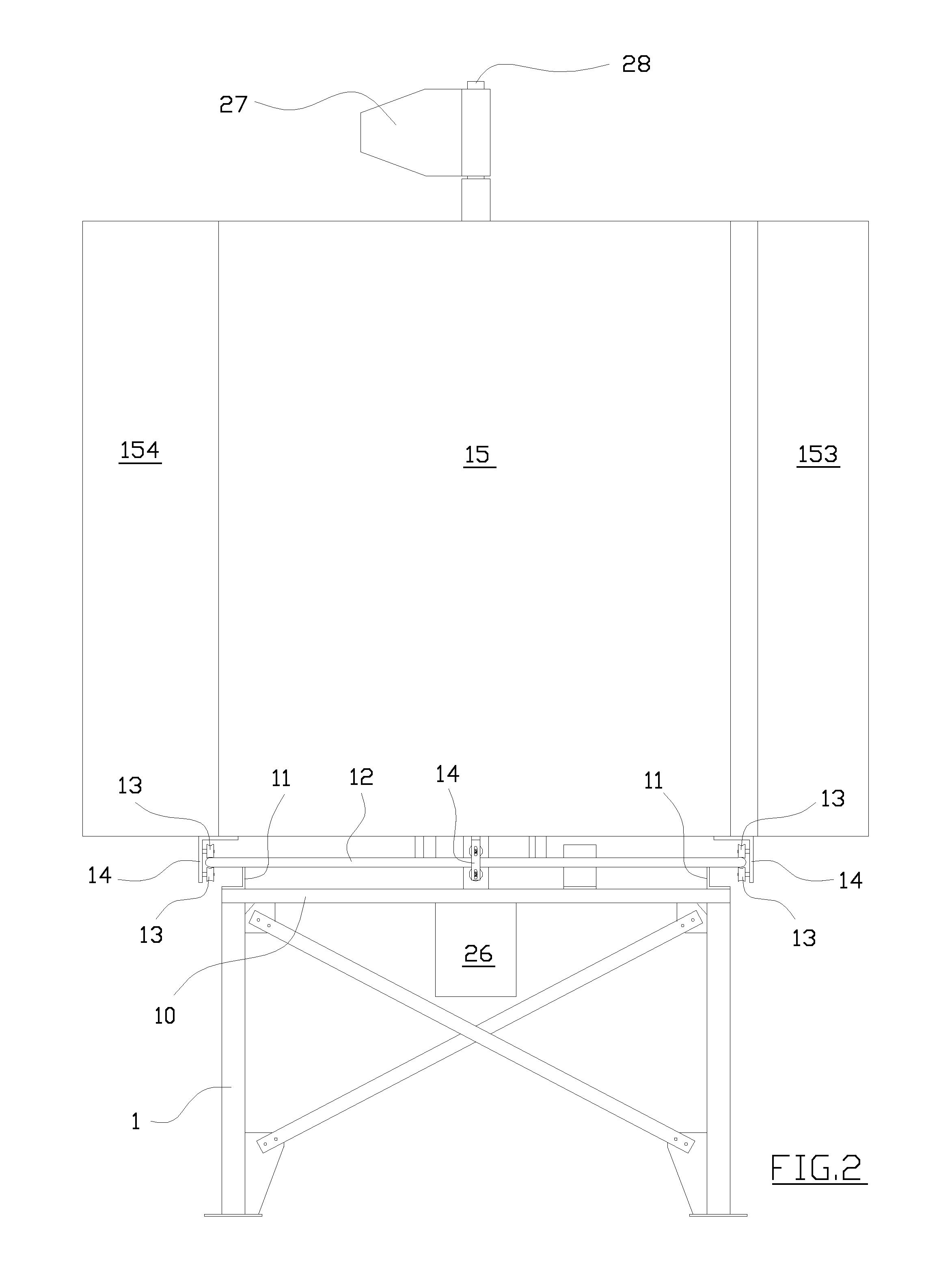
[0037]The first embodiment of FIGS. 1 to 7 comprises a base frame 1 superiorly supporting a plate 10 from which a series of peripheral brackets 11 extend upwards.

[0038]The brackets 11 support a circular ring 12, on which pairs of idle wheels 13 run, supported by brackets 14 extending from a lower circular edge of a cylindrical casing 15, the casing 15 thus being free to rotate around an axis thereof.

[0039]Fitted at the bottom of the casing is a circular rack 16 exhibiting internal teeth enmeshing with a pinion 17 of an electrical motor 18 solidly fitted to the plate 10.

[0040]The rotation of the casing 15 is thus controlled by the motor 18 in a way that will be explained herein below.

[0041]The plate 10 is fitted with a central hub 19 (FIGS. 4 and 6) which supports a shaft 22 by way of suitable bearings 20 and 21.

[0042]The shaft 22 supports, above the plate 10, a cage 23 reinforced with plates 230, from which three profiled blades 24 are formed of matching concavity.

[0043]In particula...


PUM


Abstract

A wind turbine device comprising a base frame which supports a vertical axis wind operated rotor, the axis being associated to a user device and being contained in a matchingly-dimensioned cylindrical casing exhibiting two openings, respectively an inlet and an outlet, aligned perpendicular to the rotor axis, the casing being driven to rotate about the axis by a member sensitive to the direction of the wind, such that the inlet opening is always facing into the wind.

Description

TECHNICAL FIELD[0001]The present invention is a wind turbine designed to transform wind energy into mechanical energy.BACKGROUND ART[0002]The use of turbines designed to transform wind energy into mechanical energy is well known, such devices generally being arranged in arrays comprising a significant number of turbines erected in particularly windy locations.[0003]Generators of known type usually comprise a frame designed to rotatingly support fluid-dynamic means destined to capture the wind, the fluid-dynamic means being connected by a mechanical transmission to a user device, for example a generator of electrical current.[0004]The kinetic energy of the air is generally converted into mechanical energy and subsequently into electrical energy using aerogenerators.[0005]Installations range comprises from mini- and micro-scale wind turbines which give an output of from a few hundred Watts to tens of kW of power, to medium sized installations rendering up to about a hundred kW, and fi...

Claims


Application Information

Patent Timeline
IPC IPC(8): F03D7/06F03D3/04
CPCF03D3/0427F03D3/049F05B2240/133Y02E10/74F05B2240/213F05B2240/214F05B2240/14F03D13/20
Inventor GAMBERINI, ENZO
Owner COMET
Learn More