Handlebar shock absorbing device of bicycles

Active Publication Date: 2018-03-27
DAH KEN IND
View PDF2 Cites 3 Cited by
  • Summary
  • Abstract
  • Description
  • Claims
  • Application Information

AI Technical Summary

Benefits of technology

[0010]The advantages of the present invention are that the first and second springs respectively absorb the shocks transferred from the ground to the handlebar. The downward pressure transferred to the front fork and the front wheel via the front fork is reduced, such that the front fork and the front wheel are freely moved up and down. The front fork and the front wheel are easily controlled and not affected by the force applied to the handlebar.
[0011]The first and second springs are received in the sleeve

Problems solved by technology

However, the springs in the front fork cannot absorb the shocks as expec

Method used


Image

  • Handlebar shock absorbing device of bicycles
  • Handlebar shock absorbing device of bicycles
  • Handlebar shock absorbing device of bicycles

Examples


Example

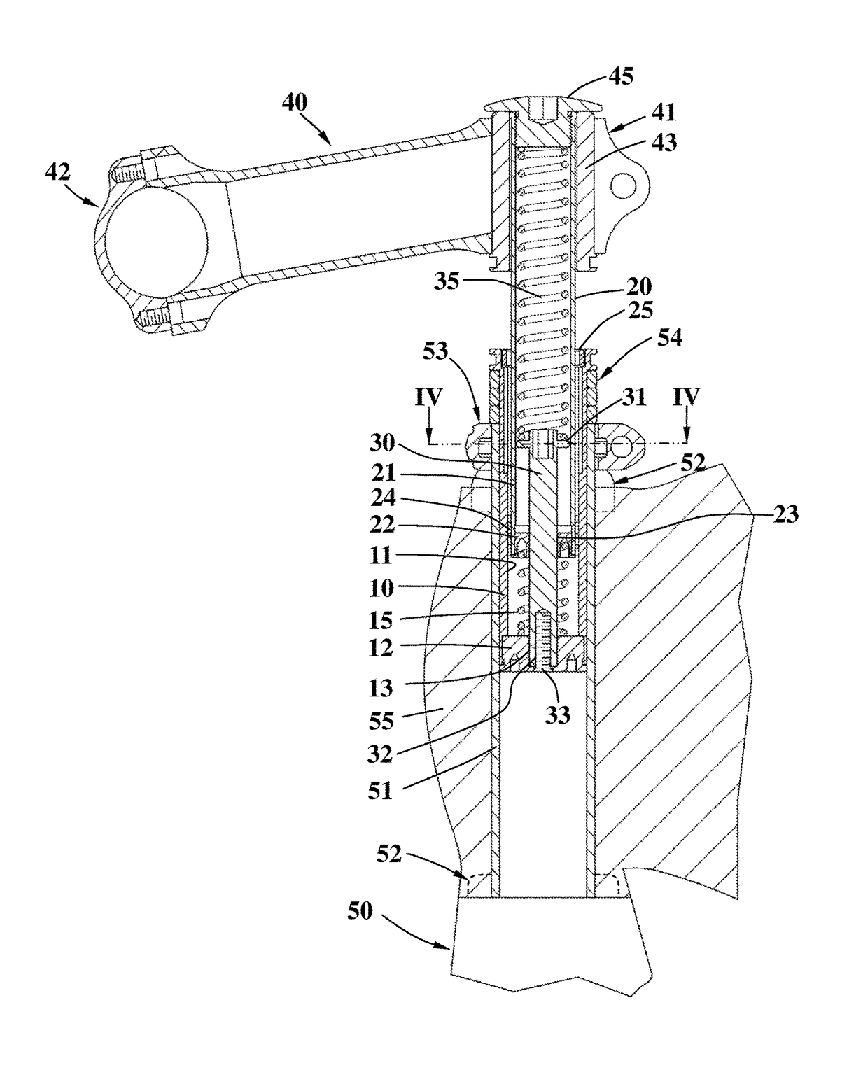
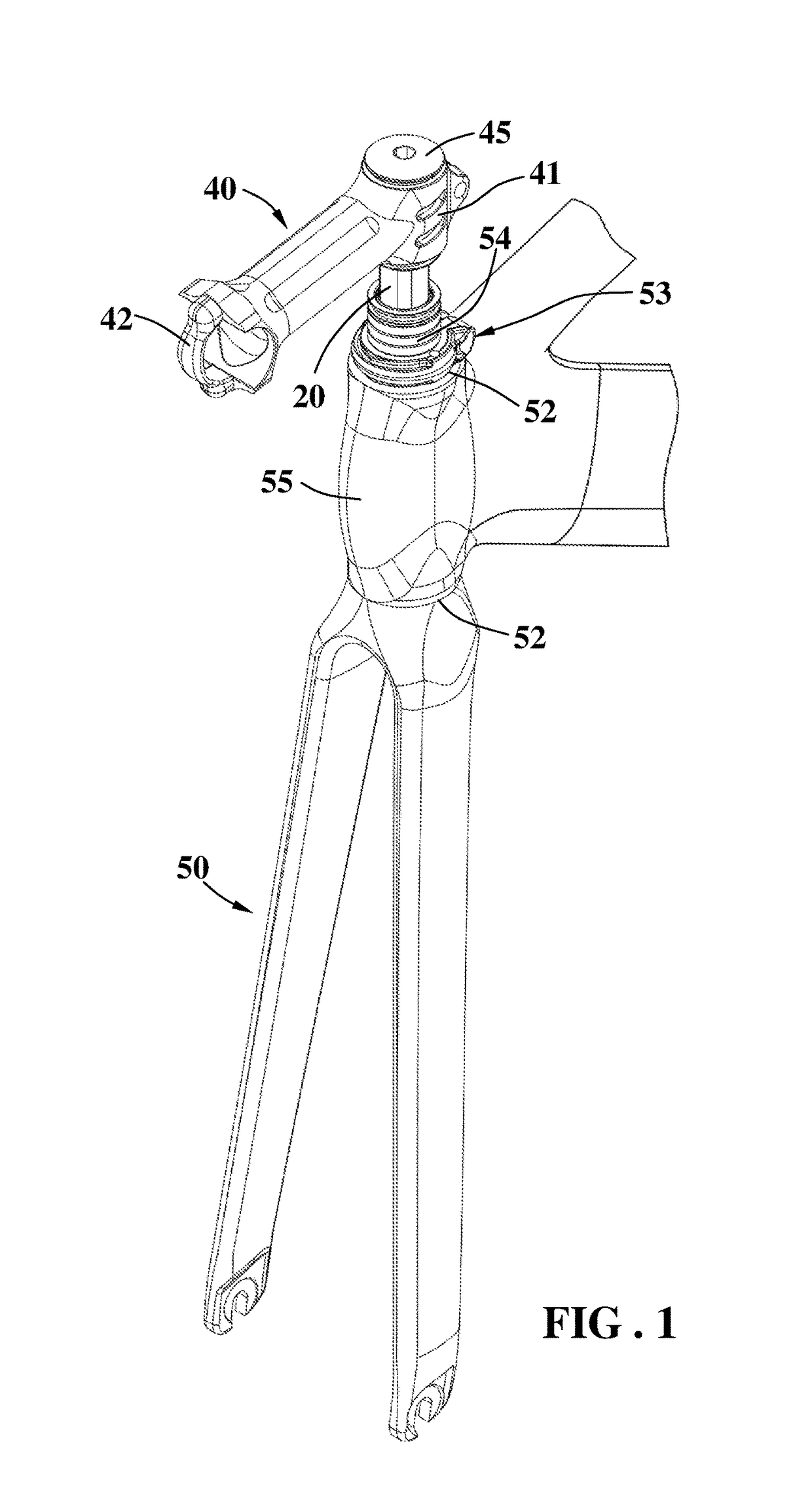
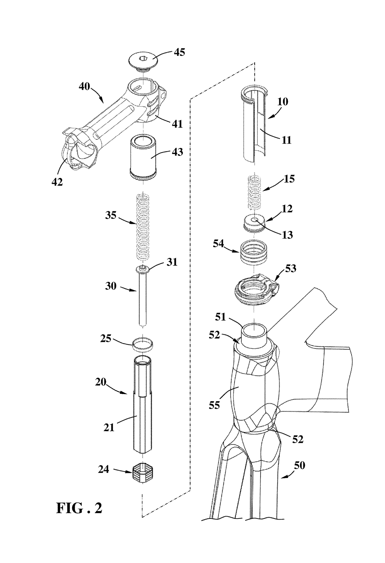
[0019]Referring to FIGS. 1 to 4, the handlebar shock absorbing device of the present invention comprises a sleeve 10 which has a first polygonal section 11 defined in the inner periphery thereof. A first end member 12 is connected to the lower end of the sleeve 10, and the sleeve 10 is inserted into a steering tube 51. A first spring 15 is axially received in the sleeve 10 and the first spring 15 is a compression spring. The lower end of the first spring 15 contacts the first end member 12. The first end member 12 has an aperture 13.

[0020]A tube 20 has a second polygonal section 21 defined in the outer periphery thereof. A second end member 22 is connected to the lower end of the tube 20. The second end member 22 has a hole 23 centrally defined therethrough. The tube 20 is inserted into the sleeve 10, and the second polygonal section 21 engaged with the first polygonal section 21 of the sleeve 10 with a polygonal bush 24 located between the first and second polygonal sections 11, 21...


PUM


Abstract

A handlebar shock absorbing device includes a sleeve in which a tube is co-rotatably inserted. A rod is inserted into the tube. A first spring is axially received in the sleeve and contacts the tube. A second spring is located in the tube and located between the rod and a cap on top of the tube. The first and second springs absorb shocks transferred to the handlebar.

Description

BACKGROUND OF THE INVENTION1. Fields of the Invention[0001]The present invention relates to a handlebar shock absorbing device, and the shock absorbing device is installed in the head tube of the bicycle.2. Descriptions of Related Art[0002]The conventional bicycle shock absorbing device for releasing shocks transferring to the handlebar includes a spring received in each of two extensions of the front fork, so that when the shocks are transferred from the ground to the handlebar, the springs absorb the shocks. However, the springs in the front fork cannot absorb the shocks as expected, and the rider still feels significant vibration from the handlebar.[0003]The present invention intends to provide a handlebar shock absorbing device which is installed in the head tube of the bicycle so as to absorb the shocks efficiently.SUMMARY OF THE INVENTION[0004]The present invention relates to a handlebar shock absorbing device and comprises a sleeve having a first polygonal section defined in ...

Claims


Application Information

Patent Timeline
IPC IPC(8): B62K21/20B62K21/14
CPCB62K21/20B62K21/14
Inventor TSAI, CHIN-SUNG
Owner DAH KEN IND
Why Eureka
Try Eureka