Fluid control device

a control device and fluid technology, applied in the direction of positive displacement liquid engines, diaphragm valves, engine diaphragms, etc., can solve the problems of difficult to apply an appropriate tension in such a way that the film is not warped or wrinkled

Active Publication Date: 2018-03-27
ALPS ALPINE CO LTD
View PDF12 Cites 2 Cited by
  • Summary
  • Abstract
  • Description
  • Claims
  • Application Information

AI Technical Summary

Benefits of technology

[0020]The fluid control device in the present invention can stretch the diaphragm part of a film facing flow paths under an appropriate tension without warps or wrinkles just by sandwiching the film between two plates and joining them together.

Problems solved by technology

However, when a film is sandwiched between two plates, the film having a smaller area than the plates, it is very difficult to apply an appropriate tension in such a way that the film is not warped or wrinkled.

Method used


Image

  • Fluid control device
  • Fluid control device
  • Fluid control device

Examples


first embodiment

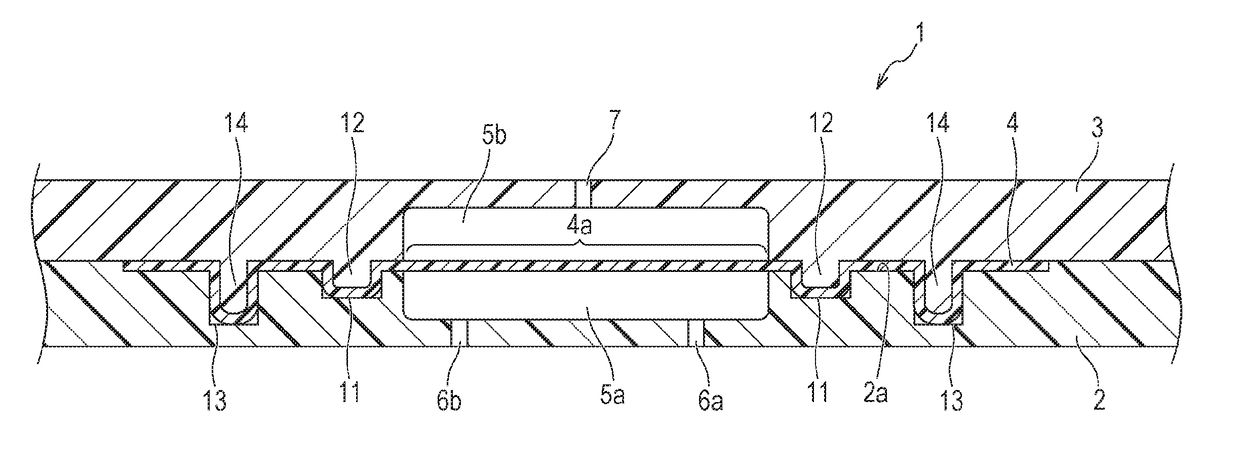
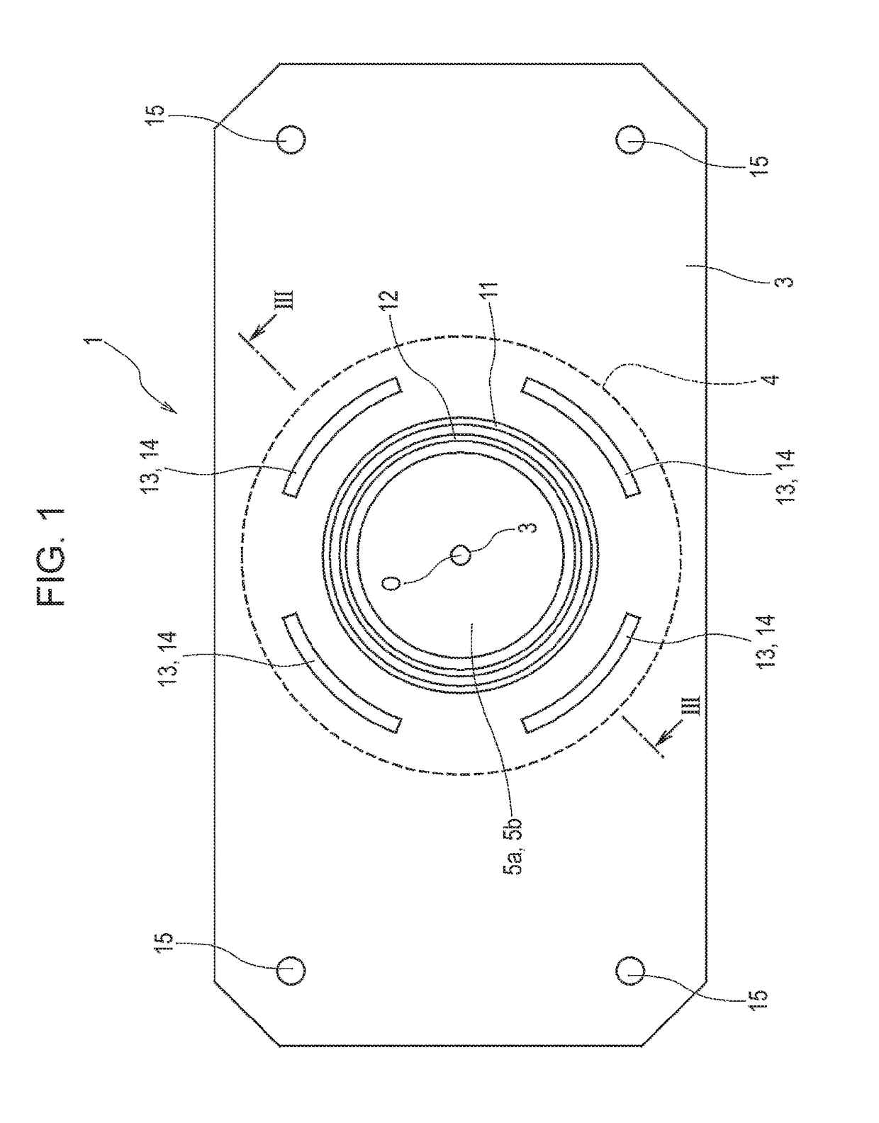
[0026]A fluid control device 1, illustrated in FIGS. 1 to 4, in the present invention, forms part of a micro flow path device. The fluid control device 1 is used to control the flow rate of a fluid.

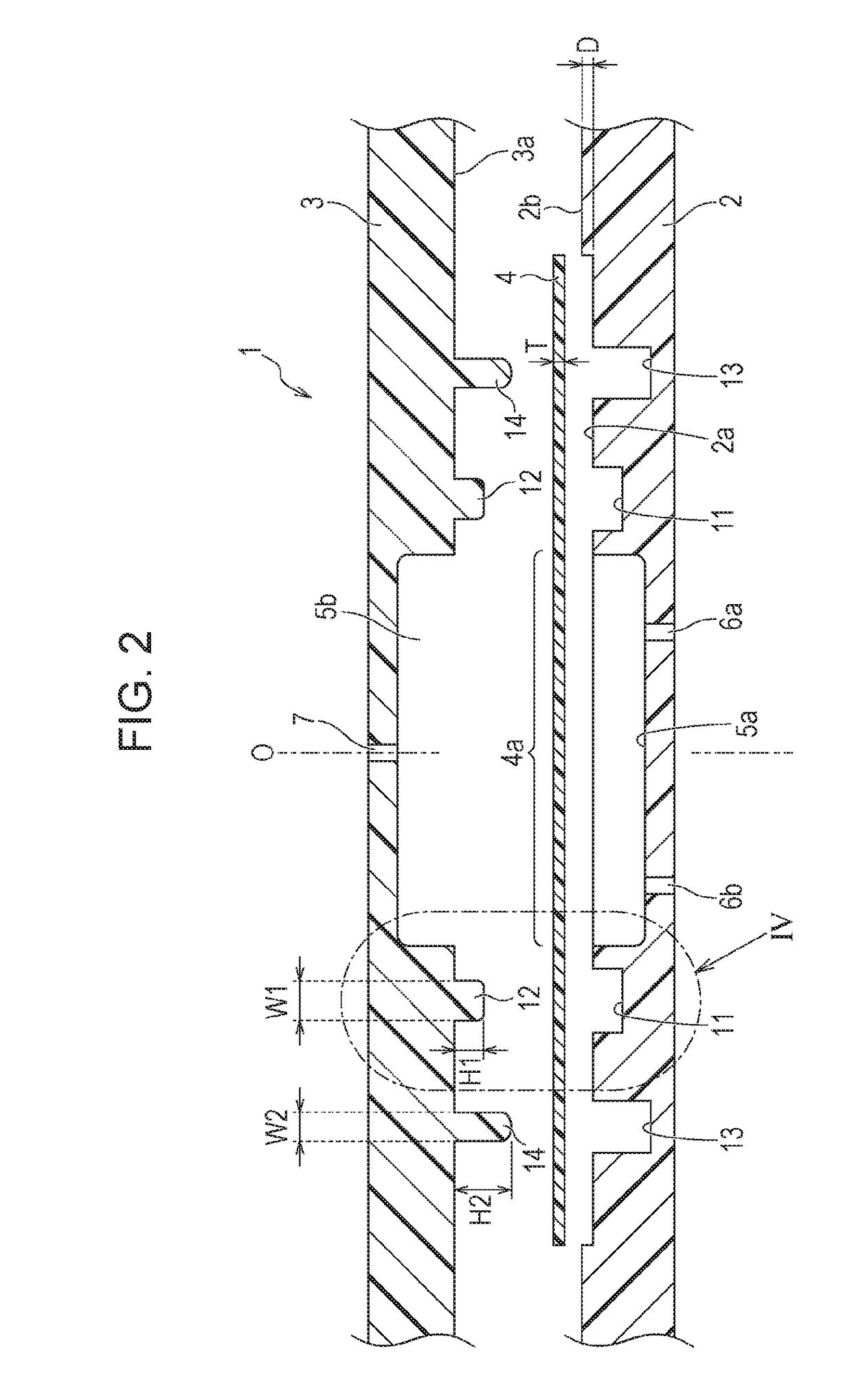
[0027]As illustrated in FIGS. 2 and 3, the fluid control device 1 has a first plate 2, a second plate 3, and a film 4, which is sandwiched between the first plate 2 and the second plate 3. The first plate 2 and second plate 3 are made of a cycloolefin polymer (COP) resin. The film 4 is preferably made of a resin material, such as a silicone resin, that has a flexibility and elasticity and the surface of which has a slight adhesion.

[0028]The fluid control device 1 is used in a reaction experiment in biological chemistry and other purposes. Therefore, the first plate 2, second plate 3, and film 4 are held with holding metal fittings or the like in a state in which the first plate 2 and second plate 3 are face-joined together as indicated in FIG. 3 without an adhesive being used, and are use...

second embodiment

[0053]Alternatively, as with a fluid control device 101 in a second embodiment illustrated in FIG. 5, outer concave parts 113 and outer convex parts 114 may have a circular cross-section and may be disposed at intervals of an equal angle around the center O.


PUM


Abstract

A film is sandwiched between a first plate and a second plate. Outer convex parts formed on the second plate are formed so that their protrusion height dimension is larger than that of an inner convex part. Each outer convex part is formed so that its width dimension is smaller than the inner convex part. When the first plate and second plate are face-joined together, the film is sandwiched between outer concave parts and the outer convex parts, after which the film is sandwiched between an inner concave part and an inner convex part and a tension is applied to a diaphragm part stretched in concave flow paths.

Description

CLAIM OF PRIORITY[0001]This application is a Continuation of International Application No. PCT / JP2015 / 051539 filed on Jan. 21, 2015, which claims benefit of Japanese Patent Application No. 2014-013102 filed on Jan. 28, 2014. The entire contents of each application noted above are hereby incorporated by reference.BACKGROUND OF THE INVENTION[0002]1. Field of the Invention[0003]The present invention relates to a fluid control device included in a so-called micro flow path device, and more particularly to a fluid control device in which a film is sandwiched between two plates and part of the film forms a diaphragm part.[0004]2. Description of the Related Art[0005]A micro flow path device is used in a reaction experiment or the like in which a small amount of fluid is used.[0006]In a micro flow path device, a fine flow path is formed in, for example, a joined part of plates. A plurality of micro flow path devices of this type are combined for use in the application. A fluid control devic...

Claims


Application Information

Patent Timeline
Patent Type & Authority Patents(United States)
IPC IPC(8): F04B43/02F16K7/17F04B45/04
CPCF04B43/02F16K7/17F04B45/04F04B53/22
Inventor ITO, JUNKOWATANABE, YASUSHI
Owner ALPS ALPINE CO LTD
Why Eureka
Try Eureka