Side-locking sliding rail assembly having an auto-opening mechanism

a technology of auto-opening and sliding rails, which is applied in the direction of bearings, shafts and bearings, bearings, etc., can solve the problems of shortening shortening the lifespan, and easy damage to the locating rod of the locating member, so as to prolong the life of the auto-opening mechanism, prevent component damage, and accurate close

Active Publication Date: 2018-04-03
GSLIDE
View PDF21 Cites 3 Cited by
  • Summary
  • Abstract
  • Description
  • Claims
  • Application Information

AI Technical Summary

Benefits of technology

[0009]The present disclosure seeks to address disadvantages in the existing prior art. It is therefore the main object of the present disclosure to provide a side-locking sliding rail assembly having an auto-opening mechanism, which enables a pawl of a locating rod of a locating member to be forced by a second compression spring into engagement with one of a series of sloping teeth to prohibit the drawer from being forced outwards by the elastic potential energy or restoring force of at least one first compression spring if the drawer does not reach the closed position when the user pushes the drawer backward from the open position toward the closed position, thus, a drawer that is not initially closed completely can be accurately closed when thereafter, the user gently applies a pressure to push the drawer backward to the closed position, assuring positive auto-opening functioning.
[0010]It is another object of the present disclosure to provide a side-locking sliding rail assembly having an auto-opening mechanism, which provides a small tooth pitch design for the sloping teeth of the auto-opening mechanism carrier plate to prevent component damage upon impact between the locating rod of the locating member and the auto-opening mechanism carrier plate, thereby prolonging the lifespan of the auto-opening mechanism.
[0011]It is still another object of the present disclosure to provide a side-locking sliding rail assembly having an auto-opening mechanism that assures positive auto-opening functioning by preventing the locating rod of the locating member from falling downward and moving to an unlatched position due to a large component dimensional tolerance or insufficient damping oil, when the drawer is not closed completely.
[0012]To achieve these and other objects, the present disclosure provides a side-locking sliding rail assembly for a drawer comprising a fixed rail, a movable rail, an intermediate rail, a sliding device, a locating member, a hook block, an actuation member, at least one first compression spring, a second compression spring and an auto-opening mechanism carrier plate. The drawer can be temporarily secured in a position that is less than fully closed, subject to engagement of a pawl of a locating rod of a locating member with at least one of a series of sloping teeth along an auto-opening mechanism carrier plate, if the drawer is not accurately closed. Thereafter, the user can gently apply a pressure to push the drawer backward to the closed position, avoiding inadvertent rebound relative to the auto-opening mechanism carrier plate under the force of the at least one first compression spring.
[0013]The small tooth pitch of the sloping teeth of the auto-opening mechanism carrier plate avoids component damage due to impact between the locating member and the auto-opening mechanism carrier plate, promoting a longer lifespan. The arrangement of a second compression spring prevents shifting of the locating member away from a temporarily held position when the sliding device is moved backward with the drawer relative to the auto-opening mechanism carrier plate. Thus, the locating rod will not be forced back toward free movement within the guide-in channel or fall downward due to a large dimensional tolerance of the second pivot pin of the locating member or insufficient damping oil. The second compression spring will bias or force the pawl of the locating rod of the locating member into engagement with at least one tooth of the sloping teeth, permitting the drawer to thereafter be pushed to a closed position to assure positive auto-opening functioning.

Problems solved by technology

However, this design still has the following minor drawbacks.
After a long use, the locating rod of the locating member can be damaged easily due to a large gap between each two adjacent grooves in the guide-in channel of the auto-opening mechanism carrier plate, such as when the locating rod of the locating member is forced into one of the grooves, and this problem will be more serious if the drawer at the movable rail carries a heavy load, shortening the lifespan.
When the auto-opening mechanism carrier plate slides backward to the end as the user closes the drawer, the locating rod of the locating member can fall downwards and shift its position due to a large dimensional tolerance of the pivot pin of the locating member or insufficient damping oil, causing the locating rod of the locating member to move backward in the original path (the guide-in channel) and leading to an auto-opening functional failure.
During backward movement of the intermediate rail, the rear end of the intermediate rail can strike against the front side of the hook block if the pushing force applied by the user is excessively large, causing the hook block to deflect or to tilt, leading to hook block damage.

Method used


Image

  • Side-locking sliding rail assembly having an auto-opening mechanism
  • Side-locking sliding rail assembly having an auto-opening mechanism
  • Side-locking sliding rail assembly having an auto-opening mechanism

Examples


Embodiment Construction

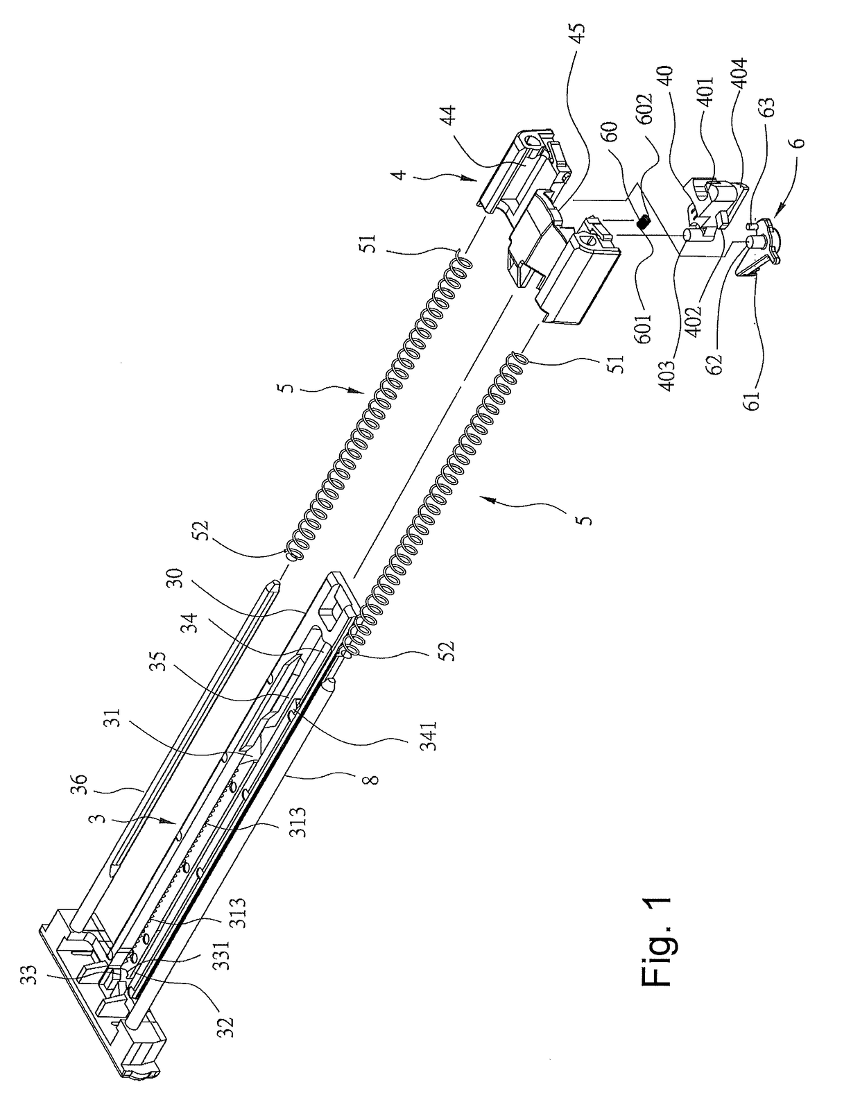
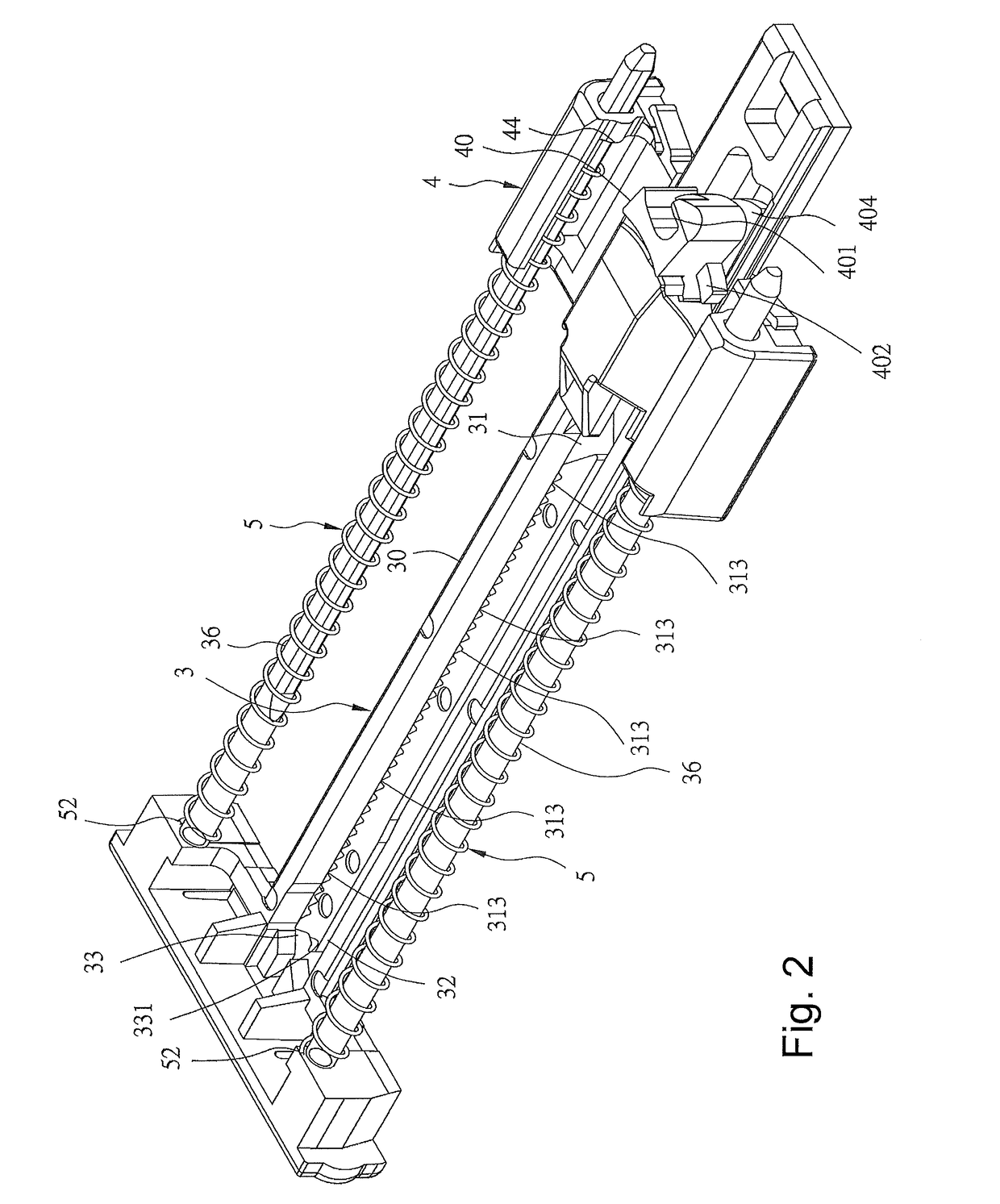
[0034]Referring to FIGS. 1-20, a side-locking sliding rail assembly having an auto-opening mechanism in accordance with the present disclosure is shown. The side-locking sliding rail assembly comprises:

[0035]a fixed rail 1 (see FIGS. 6-17) configured to be affixed to an inner sidewall of a cabinet (not shown);

[0036]a movable rail 2 (see FIGS. 6-17) configured to be affixed to a drawer (not shown) and mounted on the fixed rail 1 and being slidable with the drawer forward and backward relative to the fixed rail 1;

[0037]an intermediate rail 9 (see FIGS. 6-17) coupled between the fixed rail 1 and the movable rail 2 and being slidable forward and backward relative to the fixed rail 1 and the movable rail 2;

[0038]a sliding device 4 comprising a sliding groove 45 slidably coupled to an auto-opening mechanism carrier plate 3 for enabling the sliding device 4 to be moved forward or backward along the auto-opening mechanism carrier plate 3, a first pivot hole 41 for the connection of a hook b...


PUM


Abstract

A side-locking sliding rail assembly for a drawer consisting of a fixed rail, a movable rail, an intermediate rail, a sliding device, a locating member, a hook block, an actuation member, at least one first compression spring, a second compression spring and an auto-opening mechanism carrier plate. The drawer can be temporarily secured in a position, subject to engagement of a pawl of a locating rod of the locating member with one of a series of sloping teeth along the auto-opening mechanism carrier plate, if the drawer is not accurately fully closed. Thereafter, the user can apply a pressure to push the drawer backward to the fully closed position avoiding rebound toward the open position. The arrangement of a second compression spring prevents tilting of the locating member, so that the locating rod will not be permitted to move forward when in the guide-in channel.

Description

BACKGROUND OF THE INVENTION[0001]1. Field of the Invention[0002]The present invention relates to side-locking sliding rail assembly technology and more particularly, a side-locking sliding rail assembly having an auto-opening mechanism, which enables the drawer to be temporarily secured in position subject to engagement of a pawl of a locating member with one of a series of sloping teeth if the drawer is not accurately closed, and thus, the user can gently apply a pressure to push the drawer back to the close position avoiding rebound of the auto-opening mechanism carrier plate.[0003]2. Description of the Related Art[0004]When closing a drawer that is carried on two sliding rail assemblies having an auto-opening function, if the drawer is not completely closed, the drawer will be pushed open. Taiwan Utility M396049 discloses a hidden sliding rail assembly having an auto-opening and auto-closing buffering mechanism. According to this design, if the drawer is not completely closed, th...

Claims


Application Information

Patent Timeline
Patent Type & Authority Patents(United States)
IPC IPC(8): A47B95/00F16C29/10A47B88/463A47B88/49A47B88/50
CPCA47B88/49A47B88/50A47B88/463F16C29/10F16C2314/72
Inventor CHEN, YUNG-LIANG
Owner GSLIDE
Why Eureka
Try Eureka