
Method for manufacturing vacuum insulation glass panel and device for closing sealing cap

a technology of vacuum insulation glass and sealing cap, which is applied in the manufacture of glass making apparatus, glass making tools, and parallel plane units. it can solve the problems of affecting the manufacturing process of vacuum insulation glass panels, and affecting the quality of glass panels. it is easy to set, and the manufacturing process of glass panels of different sizes can be simplified and automated.

Active Publication Date: 2019-07-04
PARK JE IL
View PDF12 Cites 2 Cited by
  • Summary
  • Abstract
  • Description
  • Claims
  • Application Information

AI Technical Summary

Benefits of technology

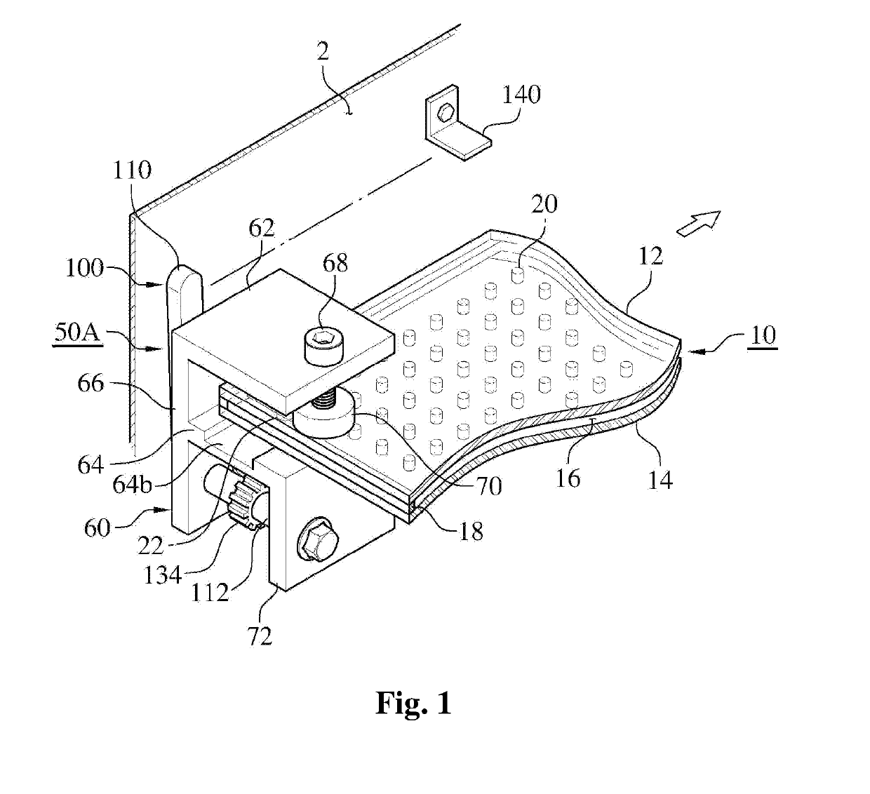
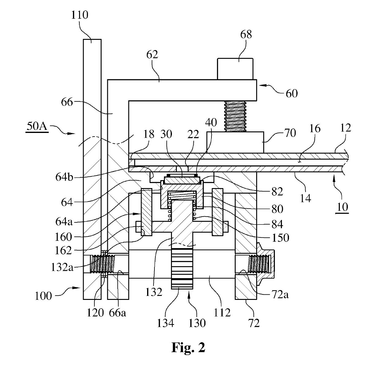
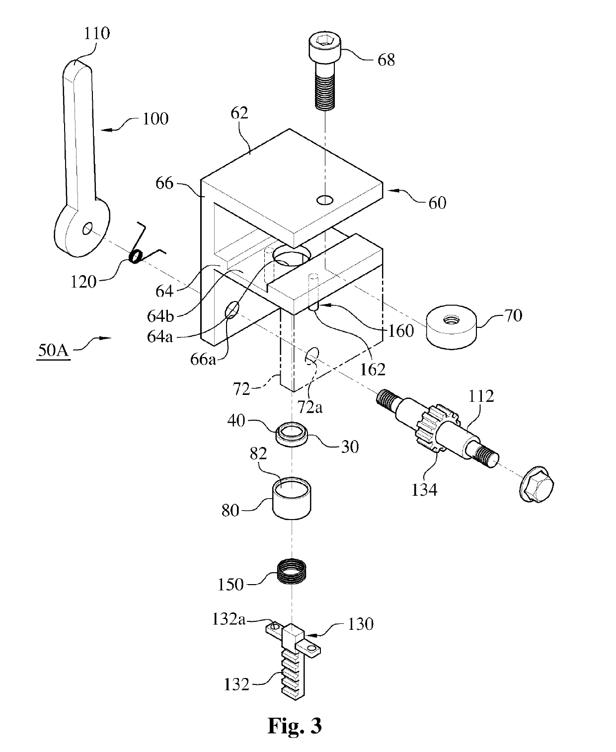
The present invention provides a method and apparatus for manufacturing vacuum insulation glass panels. The apparatus includes a holder for holding a sealing cap, which is mounted on a clamping unit and then clamped to the glass panel assembly to accurately close the exhaust hole. The holder simplifies the manufacturing process of glass panels having different sizes and prevents foreign materials from remaining in the assembly. The sealing cap is heated before putting it into the vacuum chamber, increasing heat energy efficiency. Overall, the invention allows for stable support of the sealing cap, accurate closing of the exhaust hole, and automation of the manufacturing process.

Problems solved by technology

However, the glass tube protrudes from the surface of the glass panel and may be damaged.
The vacuum insulation glass panel manufacturing method described above has various problems.
First, since the closing-off cap is arranged and held above the opening by a member such as a spring or the like, the closing-off cap may be displaced or dropped during the movement of the glass panels.
Thus, there is a possibility that the opening may not be accurately closed by the closing-off cap.
Secondly, after the opening is closed by the closing-off cap, the member may remain inside the glass panels, thereby causing noise and breakage.
Thirdly, since the position of the opening formed in the glass panels is changed depending on the size of the vacuum insulation glass panel, the setting of the plunger for pressing the closing-off cap is considerably complicated.

Method used


Image

  • Method for manufacturing vacuum insulation glass panel and device for closing sealing cap
  • Method for manufacturing vacuum insulation glass panel and device for closing sealing cap
  • Method for manufacturing vacuum insulation glass panel and device for closing sealing cap

Examples


Embodiment Construction

[0037]Other objects, specific advantages and novel features of the present invention will become more apparent from the following detailed description of preferred embodiments given in conjunction with the accompanying drawings.

[0038]Hereinafter, preferred embodiments of a vacuum insulation glass panel sealing cap closing apparatus according to the present invention will be described in detail with reference to the accompanying drawings.

[0039]Referring first to FIGS. 1 to 5, there is shown a sealing cap closing apparatus according to a first embodiment of the present invention. Referring to FIGS. 1, 2, 4 and 5, the glass panel assembly 10 includes an upper glass panel 12 and a lower glass panel 14 facing each other in parallel across a gap left therebetween. The edges of the upper and lower glass panels 12 and 14 are sealed by a seal 18, for example, a glass solder, to maintain a space 16 between the upper and lower glass panels 12 and 14 in a vacuum (depressurized) state. In the ca...


PUM

PropertyMeasurementUnit
thermal conductivityaaaaaaaaaa
elastic forceaaaaaaaaaa
pressureaaaaaaaaaa

Abstract

Provided are a method for manufacturing a vacuum insulation glass panel and a device for closing a sealing cap, the method and the device being for exhausting air between two glass panels and sealing the same. The method for manufacturing a vacuum insulation glass panel, according to the present invention, heats the glass solder applied on the sealing cap before being put into a vacuum chamber, and then presses, by the operation of the elevating device, the sealing cap put into the vacuum chamber so as to join the sealing cap around the exhaust hole. The holder having the sealing cap is mounted in the clamping unit, and then the clamping unit is clamped to the glass panel assembly, thereby enabling the exhaust hole to be accurately closed with the sealing cap.

Description

TECHNICAL FIELD[0001]The present invention relates to a vacuum insulation glass panel, and more particularly, to a vacuum insulation glass panel manufacturing method for exhausting an air present between two glass panels and sealing a space between two glass panels, and a sealing cap closing apparatus.BACKGROUND ART[0002]A vacuum insulation glass panel is used as a window or an outer wall to improve the efficiency of heating and cooling of a building, a house or the like. The vacuum insulation glass panel includes two glass panels which are spaced apart from each other in parallel. The edges of the glass panels are sealed by a seal to keep the space between the two glass panels at a reduced pressure lower than the atmospheric pressure. The space between the glass panels is maintained by a plurality of spacers.[0003]An opening or an exhaust hole is formed in any one of the glass panels to form a vacuum space between the glass panels by pumping out or exhausting an air. A glass tube i...

Claims


Application Information

Patent Timeline
Patent Type & Authority Applications(United States)
IPC IPC(8): E06B3/663E06B3/673C03B23/24
CPCE06B3/66342E06B3/67304E06B3/67339E06B3/66333C03B23/24E06B2003/66338C03C27/06E06B3/66E06B3/673E06B3/677E06B3/6775E06B3/6612Y02A30/249Y02B80/22
Inventor PARK, JE IL
Owner PARK JE IL
Learn More