System controlling electric power and system controlling valve

a technology of electric power and system control, applied in the direction of electric controllers, coupling device connections, instruments, etc., can solve the problems of increasing the possibility of electric leakage, affecting the operation of the system, so as to prevent the consumption of gas or city water, and prevent the consumption of power and fire risk. , the effect of preventing gas poisoning

Inactive Publication Date: 2010-09-02
WELLBAS LTD
View PDF9 Cites 3 Cited by
  • Summary
  • Abstract
  • Description
  • Claims
  • Application Information

AI Technical Summary

Benefits of technology

[0020]With the above-described construction, the present invention can properly interrupt a standby power of an outlet when a user is absent, thereby preventing consumption of power and fire risk. Also, the present invention can properly close a pipeline valve, thereby preventing gas poisoning, fire risk and waste of gas or city water.
[0021]Since a signal transmitting unit having a pyroelectric sensor and a timer is easily connected to or disconnected from a signal receiving unit of an outlet, and the signal transmitting unit is adapted to be compatible with a plurality of outlet devices and a plurality of pipeline valve devices, it is not necessary to install an expensive signal transmission device in every application one by one, which is economical in expense.
[0022]In addition, a user can selectively control an outlet or a pipeline valve, if necessary, and wanted outlets and pipeline valves can be collectively controlled at a time.

Problems solved by technology

Such a standby power not only has a bad influence on the lifetime of an electric / electronic appliance, but also plays a role in power consumption.
In addition, the standby power has the problem of increasing the possibility of an electric leakage.
In order to interrupt the standby power, users should fully unplug electronic appliances in a standby mode from outlets one by one, which is a laborious task.
In addition, in the case where the electronic appliances are not unplugged due to user's carelessness, it is not possible to interrupt the standby power.
More specifically, in the case where the valve of a combustible gas pipeline is not closed when a user is absent, the risk of a fire caused by gas leakage is highly increased.
However, in the case where a system for automatically interrupting the standby power or closing the gas valve is installed in all outlets and gas valves, the number of sensors is increased to incur expenses, which leads in an inefficient drawback.

Method used


Image

  • System controlling electric power and system controlling valve
  • System controlling electric power and system controlling valve
  • System controlling electric power and system controlling valve

Examples


Embodiment Construction

[0032]Hereinafter, exemplary embodiments of the present invention will be described with reference to the accompanying drawings.

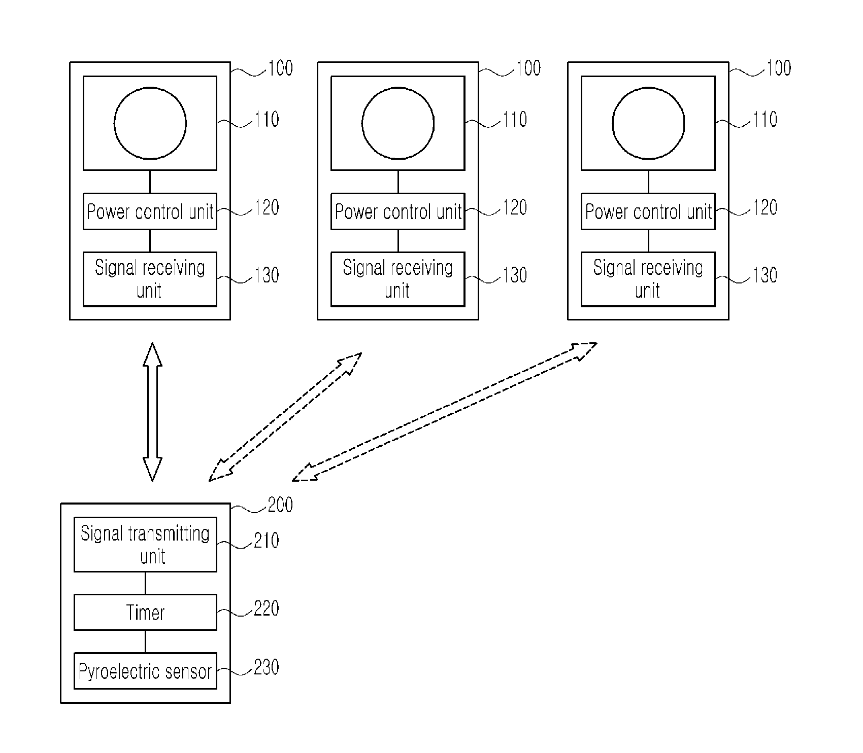
[0033]FIG. 1 is a block diagram illustrating an outlet power control system according to an embodiment of the present invention. The outlet power control system mainly includes an outlet device 100 and a signal transmission device 200.

[0034]The outlet device 100 includes an outlet unit 110, a power control unit 120, and a signal receiving unit 130. The signal transmission device 200 includes a signal transmitting unit 210, a timer 220 and a pyroelectric sensor 230.

[0035]One outlet device 100 may be connected to one signal transmission device 200, but several outlet devices 100 may be connected to one signal transmission device 200, as shown in FIG. 1. In this instance, the signal transmission device 200 and the outlet device 100 may be connected to each other by wire or wirelessly.

[0036]The outlet unit 110 receives a plug of an external electronic appliance...


PUM


Abstract

Disclosed is a system for interrupting an electric power of an outlet or closing a gas valve through detection of the absence of a user. The system includes a signal transmission device installed on an outside of the outlet and a gas valve device. The signal transmission device detects the existence of the user to output the gas valve device receive the control signal to control the flow of connected to signal an electric power or gas.

Description

TECHNICAL FIELD[0001]The present invention relates to a system for interrupting an electric power of an outlet or closing a gas valve through detection of the absence of a user.BACKGROUND ART[0002]Although an electronic appliance connected to an outlet is turned off, a small quantity of electric current is consumed, which is called a “standby power”. Such a standby power not only has a bad influence on the lifetime of an electric / electronic appliance, but also plays a role in power consumption. In addition, the standby power has the problem of increasing the possibility of an electric leakage.[0003]In order to interrupt the standby power, users should fully unplug electronic appliances in a standby mode from outlets one by one, which is a laborious task. In addition, in the case where the electronic appliances are not unplugged due to user's carelessness, it is not possible to interrupt the standby power. Consequently, a system is required for interrupting the standby power, if a us...

Claims


Application Information

Patent Timeline
Patent Type & Authority Applications(United States)
IPC IPC(8): G05B11/01
CPCF23K5/007H01R13/70F23N5/242
Inventor LEE, KEUN-JIN
Owner WELLBAS LTD
Why Eureka
Try Eureka