Thermal insulation pipe joint structure and construction method of thermal insulation pipe joint

A construction method and joint structure technology, applied in the direction of pipes/pipe joints/fittings, heat preservation, and protection of pipes through heat insulation, etc., can solve problems such as potential safety hazards, use of open flame pipes, and difficult construction requirements

Inactive Publication Date: 2013-11-20
BEIJING HTN PIPELINE EQUIP
View PDF6 Cites 3 Cited by
  • Summary
  • Abstract
  • Description
  • Claims
  • Application Information

AI Technical Summary

Problems solved by technology

[0002] The form of prefabricated direct-buried insulation pipes in the traditional central heating / cooling field is that the medium pipe is a steel pipe, the insulation layer is a polyurethane foam layer, and the outer protection pipe is made of high-density polyethylene outer protection pipe. The insulation pipe has good insulation performance. And the construction is convenient, but this type of pipeline will use open flames during the construction of the joints to bring serious safety hazards to the pipeline construction and installation operations, and the construction requirements are difficult. Therefore, it is necessary to develop a new product to further meet the requirements of pipelines in complex construction environments. fire protection requirements

Method used


Image

  • Thermal insulation pipe joint structure and construction method of thermal insulation pipe joint
  • Thermal insulation pipe joint structure and construction method of thermal insulation pipe joint
  • Thermal insulation pipe joint structure and construction method of thermal insulation pipe joint

Examples


Embodiment Construction

[0024] In order to further explain the technical means and effects adopted by the present invention to achieve the intended purpose of the invention, the specific implementation methods, Steps, structures, features and their functions are described in detail.

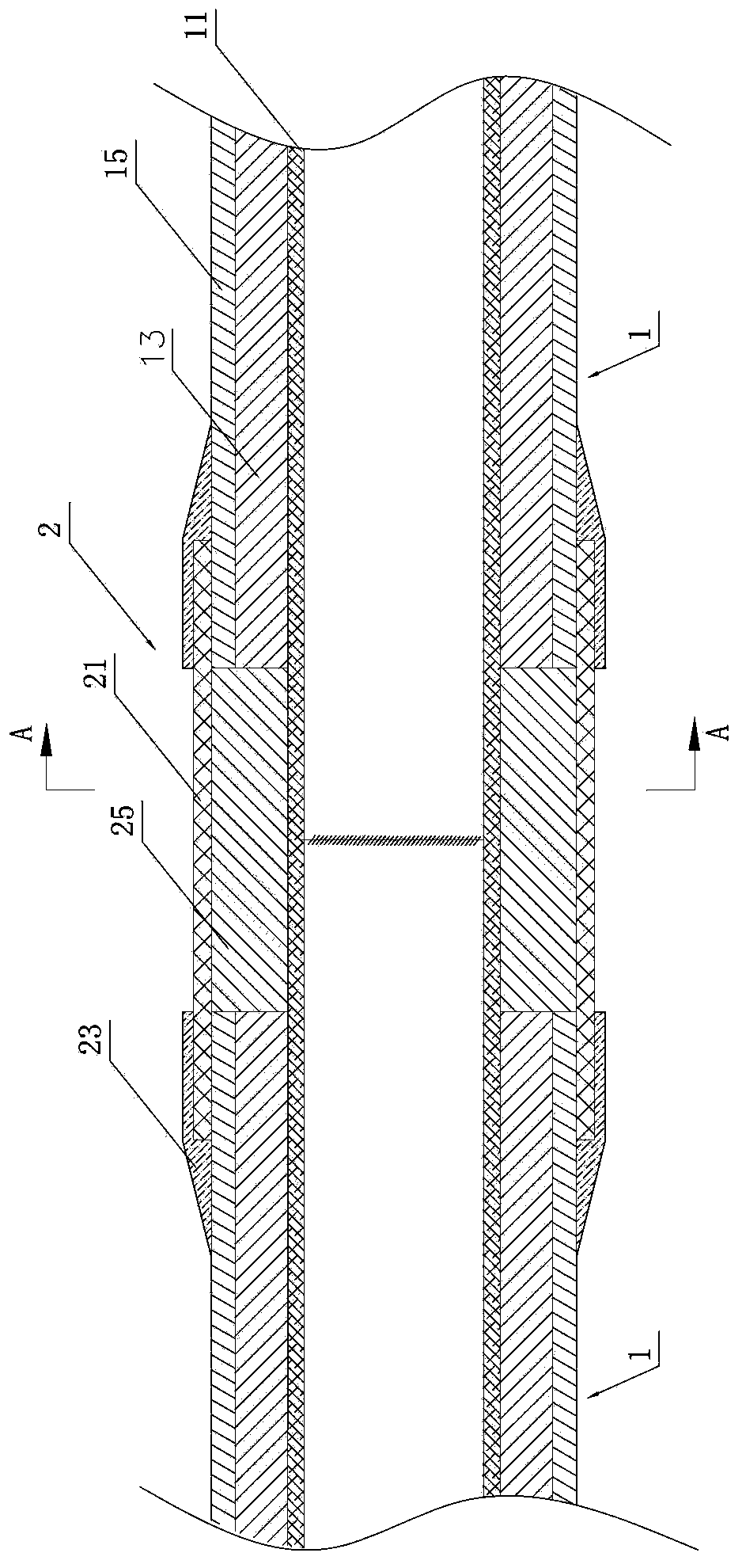
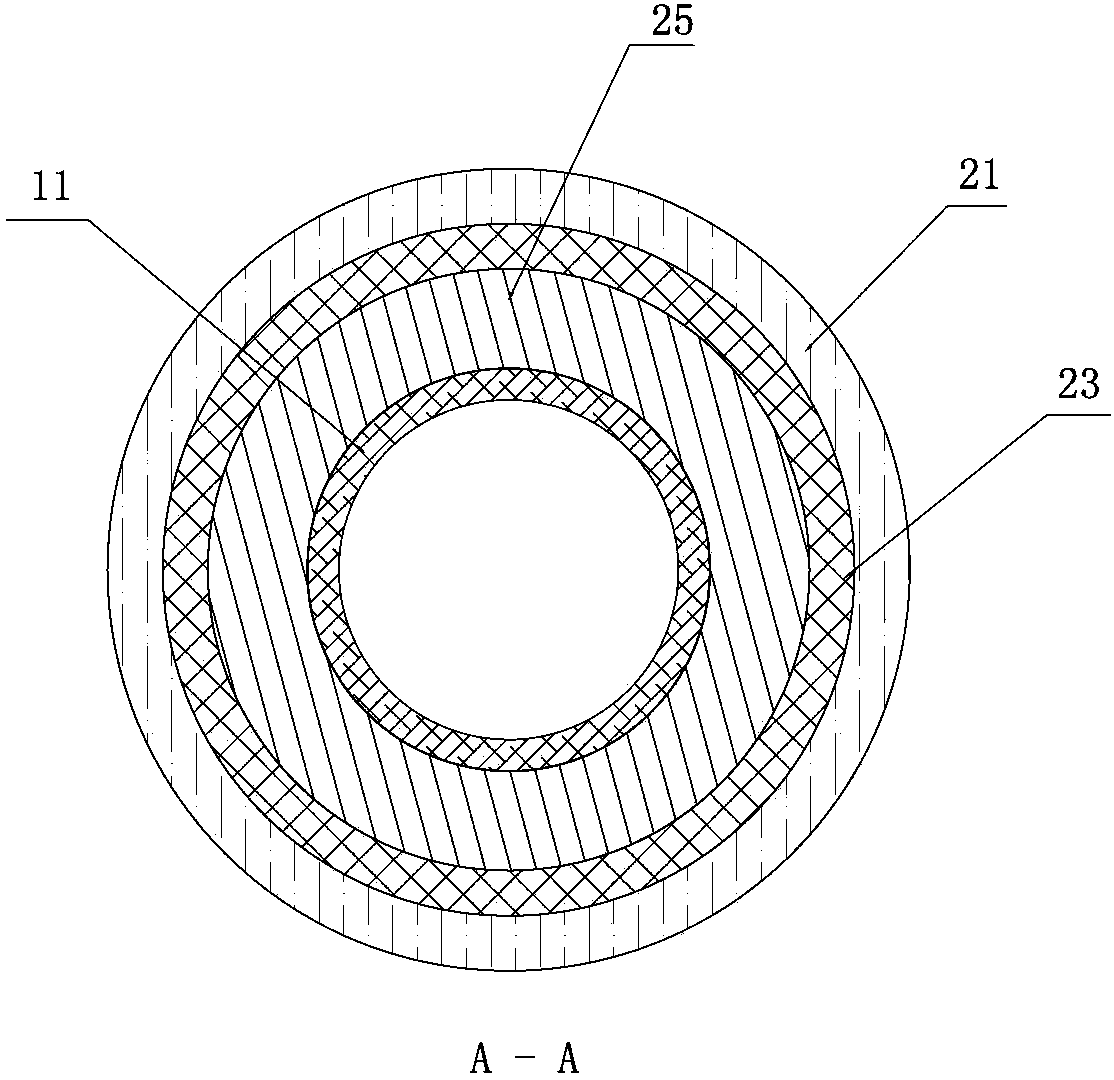
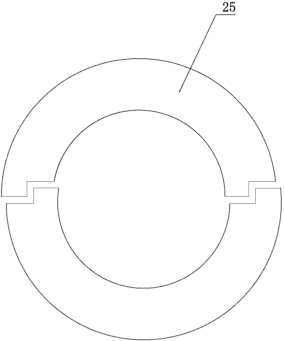
[0025] see figure 1 , figure 2 , image 3 Shown are respectively the axial sectional schematic diagram, the radial sectional schematic diagram, and the thermal insulation layer prefabricated tile structure schematic diagram of the use state of the thermal insulation pipe joint of the present invention. The thermal insulation pipe joint 2 of the present invention is suitable for the prefabricated thermal insulation pipe 1 .

[0026] In one embodiment, the prefabricated thermal insulation pipe 1 is a working pipe, an insulation layer 13 and an outer sheath 15 in sequence from the inside to the outside. The working pipe 11 is a steel pipe or a plastic pipe; the insulation layer 13 is a foam insulation layer, preferabl...


PUM


Abstract

The invention relates to a thermal insulation pipe joint structure and a construction method of a thermal insulation pipe joint. The thermal insulation pipe joint structure is used for connection of prefabricated thermal insulation pipes and comprises a glass fiber reinforced plastic sleeve, manually painted glass fiber reinforced plastics and a joint thermal insulation layer, wherein the two ends of the glass fiber reinforced plastic sleeve are coated by the manually painted glass fiber reinforced plastics, and the joint thermal insulation layer is formed inside the glass fiber reinforced plastic sleeve. The construction method of the thermal insulation pipe joint comprises the following steps: step 1, the glass fiber reinforced plastic sleeve is provided, and the joint of two prefabricated thermal insulation pipes is sleeved with the glass fiber reinforced plastic sleeve, wherein the two prefabricated thermal insulation pipes are connected in advance; step 2, the two ends of the glass fiber reinforced plastic sleeve are coated by the manually painted glass fiber reinforced plastics, wherein the manually painted glass fiber reinforced plastics extend to outer protective layers of the prefabricated thermal insulation pipes; step 3, the joint thermal insulation layer is formed in the glass fiber reinforced plastic sleeve; step 4, filling holes and exhaust holes in the glass fiber reinforced plastic sleeve are sealed. According to the thermal insulation pipe joint structure and the construction method of the thermal insulation pipe joint, no naked flame is needed for site operation, and therefore the fire risk caused by naked flames in a construction process in a limited space can be effectively eradicated.

Description

technical field [0001] The invention relates to an insulation pipe joint structure and a construction method for an insulation pipe joint, in particular to an insulation pipe joint structure and a construction method for an insulation pipe joint that does not require an open flame for on-site construction. Background technique [0002] The form of prefabricated direct-buried insulation pipes in the traditional central heating / cooling field is that the medium pipe is a steel pipe, the insulation layer is a polyurethane foam layer, and the outer protection pipe is made of high-density polyethylene outer protection pipe. The insulation pipe has good insulation performance. And the construction is convenient, but this type of pipeline will use open flames during the construction of the joints to bring serious safety hazards to the pipeline construction and installation operations, and the construction requirements are difficult. Therefore, it is necessary to develop a new product...

Claims


Application Information

Patent Timeline
IPC IPC(8): F16L59/18
Inventor 周抗冰
Owner BEIJING HTN PIPELINE EQUIP
Why Eureka
Try Eureka