Method for producing a hydrophobic element and use thereof

a technology of hydrophobic elements and hydrophobic coatings, which is applied in the field of manufacturing hydrophobic coating elements, can solve the problems of not being able to meet the requirements of the surface it covers, unable to preserve the initial shape in the face of time and humidity, and unable to meet the requirements of the required requirements at the same time. to achieve the effect of ensuring the impermeability of the surface it covers

Inactive Publication Date: 2020-04-02
CELLOZ
View PDF0 Cites 3 Cited by
  • Summary
  • Abstract
  • Description
  • Claims
  • Application Information

AI Technical Summary

Benefits of technology

[0012]The present invention aims to overcome all or a portion of the disadvantages of the prior art mentioned above by proposing a method for manufacturing a hydrophobic covering element, and a hydrophobic covering element, mainly or entirely coming from sustainably renewable resources, thus falling within the criteria of sustainable development and safety for humans and the environment while remaining economical, and allowing to ensure the impermeability of the surface that it covers.

Problems solved by technology

None of these products of the prior art can preserve its initial shape in the face of time and humidity or allow to ensure durable impermeability of the surface onto which they are applied.
The bitumen and the thermosetting resins come from fossil resources, the use of which has a negative effect on the environment and on humans.
None of the current products allow to simultaneously meet all of the required needs, namely ensuring impermeability without being harmful to the environment and to humans.

Method used


Image

  • Method for producing a hydrophobic element and use thereof
  • Method for producing a hydrophobic element and use thereof
  • Method for producing a hydrophobic element and use thereof

Examples


second embodiment

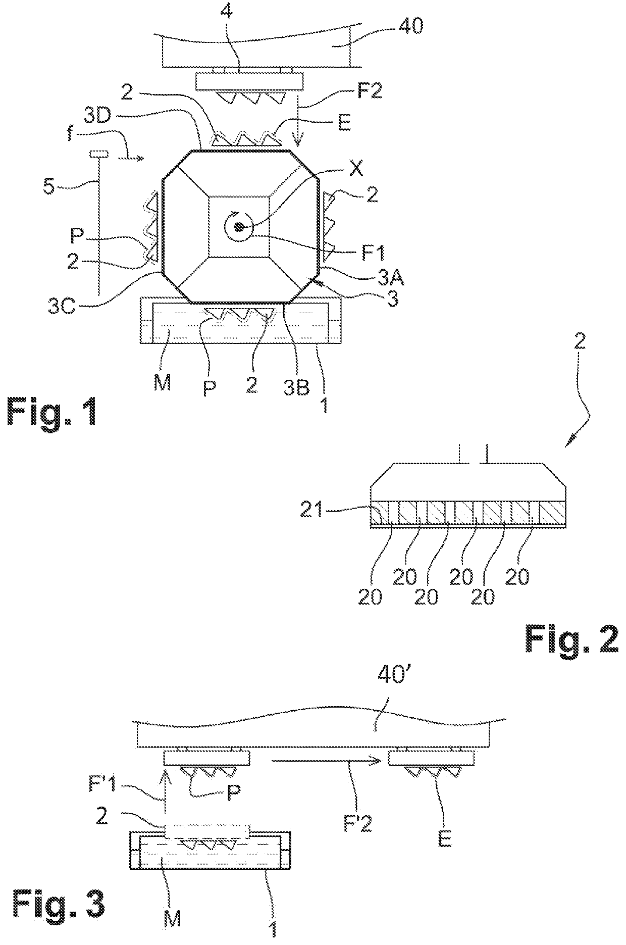
[0198]In a second embodiment, illustrated in FIG. 3, a mould 2 is immersed, under vacuum, in the tank 1 comprising the mixture M, then the mould 2, comprising a portion P of the mixture M, carries out a movement of vertical translation according to the arrow F′1 in order to remove the mould 2 from the tank 1.

[0199]Then, the mould 2 carries out a movement of horizontal translation in the direction of a belt conveyor (not shown), according to the arrow F′2, until a moulded element E is obtained.

[0200]The moulded element E is then deposited on the belt conveyor (not shown), after creation of an overpressure (stoppage of the vacuum) in the mould 2.

[0201]The mould 2 is suspended from a plate 40′, by elements allowing its vertical and horizontal movement.

[0202]The belt conveyor allows to move the moulded element E in the direction of a pressing system 6 (FIG. 5).

third embodiment

[0203]In a third embodiment illustrated in FIG. 4, a mould 2 is immersed, under vacuum, in the tank 1 comprising the mixture M, then the mould 2 carries out a movement of vertical translation according to the arrow F″1 and a movement of rotation of 180° according to the arrow F″2, in such a way as to present the moulded element E opposite a transfer counter-mould 4 as described with regard to FIG. 1.

first embodiment

[0204]The transfer of the moulded element E from the forming mould 2 to the transfer counter-mould 4 takes place in the same way as above, in the

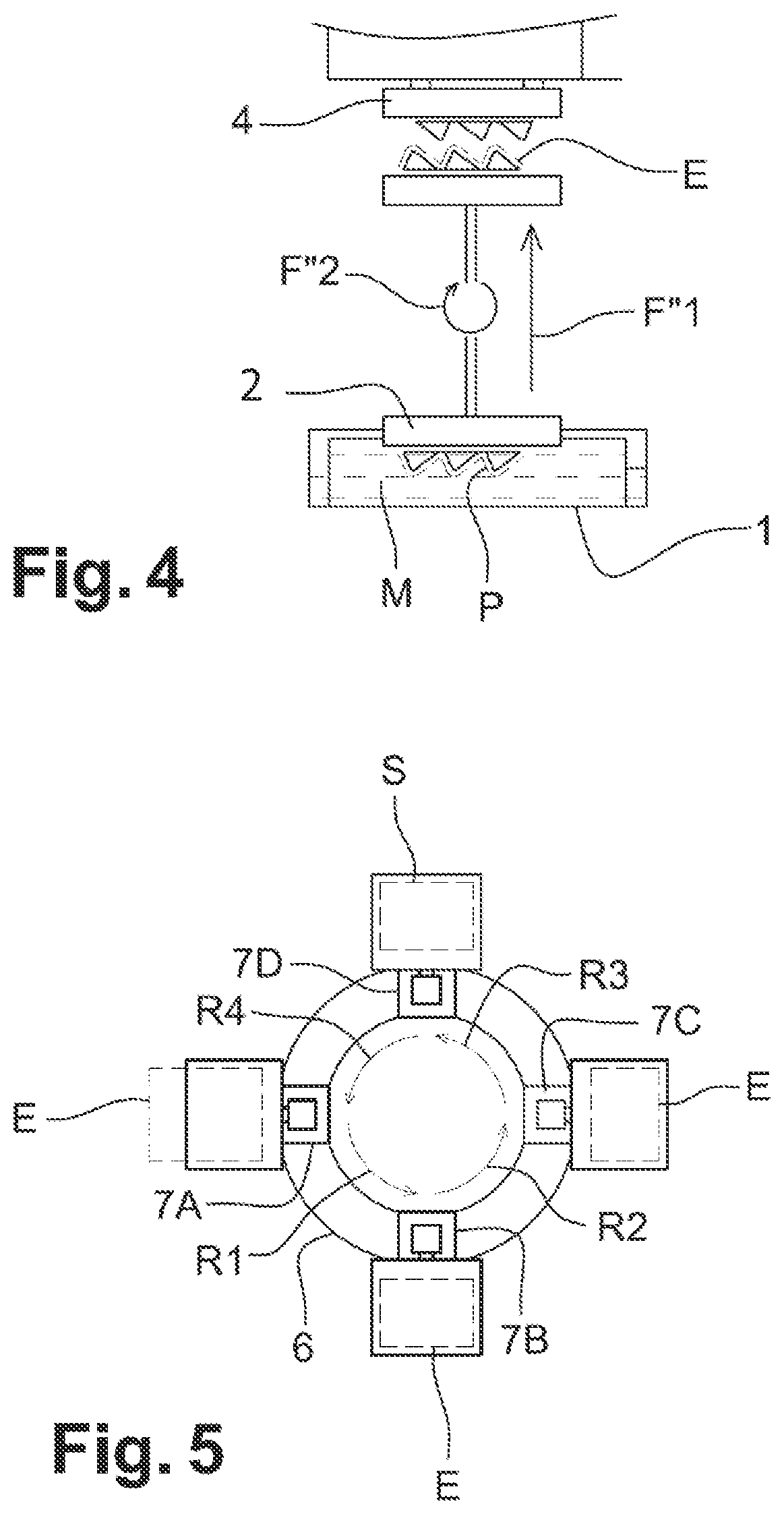
[0205]FIG. 5 shows that the moulded element E is transferred to a carrousel pressing system 6.

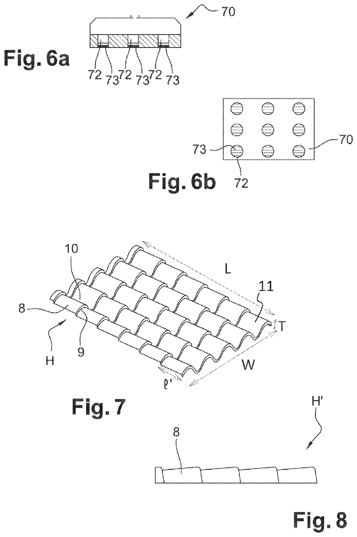
[0206]The carrousel pressing system 6 comprises four pressing mould 70 (FIGS. 6a, 6b) and counter-mould (not shown) pairs 7A, 7B, 7C, 7D.

[0207]More precisely, the moulded element E is transferred into a first pressing mould and counter-mould pair 7A in which the mould and counter-mould are pressed against one another, under vacuum, the mould and counter-mould being heated to a temperature of between 160 and 280° C.

[0208]The carrousel pressing system 6 then carries out a succession of rotation by 90° in the anti-clockwise direction, arrows R1, R2, R3, R4, in such a way that each pair 7A, 7B, 7C, 7D can receive a moulded element E.

[0209]When the pair 7A has carried out three rotations of 90°, a dried and densified element S is obtained.

[0210]The moul...


PUM

PropertyMeasurementUnit
thicknessaaaaaaaaaa
sizeaaaaaaaaaa
sizeaaaaaaaaaa

Abstract

A method for producing a hydrophobic element is disclosed and includes the following steps: a) preparing a mixture of water and an organic material from sustainably renewable resources, b) moulding the mixture prepared in step a) to obtain a moulded element, c) drying and densifying the moulded element obtained in step b) to obtain a dried and densified element-, and d) impregnating to the core the dried and densified element obtained in step c) with a binder composed of organic materials from sustainably renewable resources. A covering hydrophobic element containing more than 90%, and preferably more than 99%, of an organic material from sustainably renewable resources is also disclosed.

Description

TECHNICAL FIELD OF THE INVENTION[0001]The invention aims to manufacture a hydrophobic covering element from biosourced materials, and more particularly from organic materials coming from the resources that are sustainably renewable.[0002]“Biosourced material” means a material coming from plant or animal biomass.[0003]“Organic materials coming from sustainably renewable resources” means all of the chemical compounds formed by organic molecules found in the natural environments, of terrestrial or marine origin, and the stock of which can be replenished over a short period on the human time scale, by being renewed at least as fast as it is consumed, for example the various livestock or crop resources (biomass).[0004]The covering element can be used to cover at least a portion of an inner surface, like a wall and / or a ceiling, or a surface in contact with the outside, such as roofing or cladding, in order to protect this surface from humidity or from inclement weather.[0005]The covering...

Claims


Application Information

Patent Timeline
Patent Type & Authority Applications(United States)
IPC IPC(8): B27N1/00B27N3/00B27N3/18B27N7/00B27K3/50E04D1/26E04D3/32B27K3/02
CPCB27N7/005B27K3/0214B27K3/50E04D3/32E04D1/26B27N3/18B27N1/006B27N3/002B27K2240/70B27N1/00B27N3/00B27N3/007B27N5/00B27N9/00D21J3/00E04F13/0871E04F13/16
Inventor RUFFENACH, FRANÇOIS
Owner CELLOZ
Why Eureka
Try Eureka