Line leadthrough for the leadthrough of lines through a component

a leadthrough and leadthrough technology, applied in the direction of electrical equipment, building components, construction, etc., can solve the problems of weak mechanical forces between the wall and the line routed, cracks and gaps may be formed in the filling material, and the previous approach of filling the intermediate space between the line and the inner wall of the passage opening is not optimal

Active Publication Date: 2018-09-06
HILTI AG
View PDF2 Cites 0 Cited by
  • Summary
  • Abstract
  • Description
  • Claims
  • Application Information

AI Technical Summary

Benefits of technology

[0031]Furthermore, the closure element may be formed either in one piece with a slit extending in the direction of axial extent of the line opening or in multiple pieces. This permits simple mounting of closure element 5 around line 4.

Problems solved by technology

In the fire situation, stresses may be caused by heat generation, in turn leading to strong mechanical forces between the wall and the line routed through it.
Thereby a relative offset may develop between the line and the wall, whereby cracks and gaps may be formed in the filling material.
In particular, considerable displacements between the line and the wall may develop during earthquakes, so that the previous approach of simply filling the intermediate space between the line and the inner wall of the passage opening with a filling material is not optimum.
The filling material may detach, tear or break due to the occurring stresses, whereby the required impermeability is impaired.
In particular, a relative displacement of the line perpendicular to the wall may lead to partial or complete detachment of the filling material from the line and / or from the passage opening or to tearing of the filling material.
Cable boxes common on the market are intended to route the line either through a combination of solid plastic and sealing material, although thereby the relative mobility of the line is considerably restricted, and so, in the event of violent shaking, damage to the cable box is almost unavoidable and impermeability to gas is no longer assured.
Furthermore, intumescent lamellas may be provided, which indeed ensure improved mobility of the routed line but do not have adequate impermeability to smoke gas.

Method used


Image

  • Line leadthrough for the leadthrough of lines through a component
  • Line leadthrough for the leadthrough of lines through a component
  • Line leadthrough for the leadthrough of lines through a component

Examples


Embodiment Construction

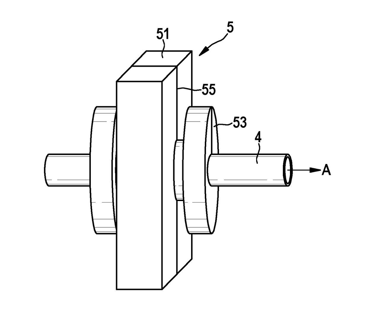
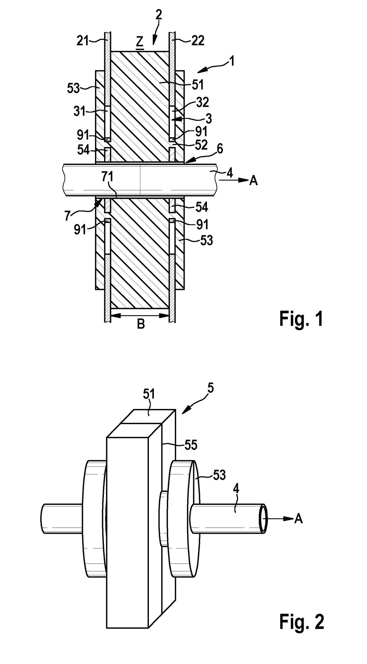
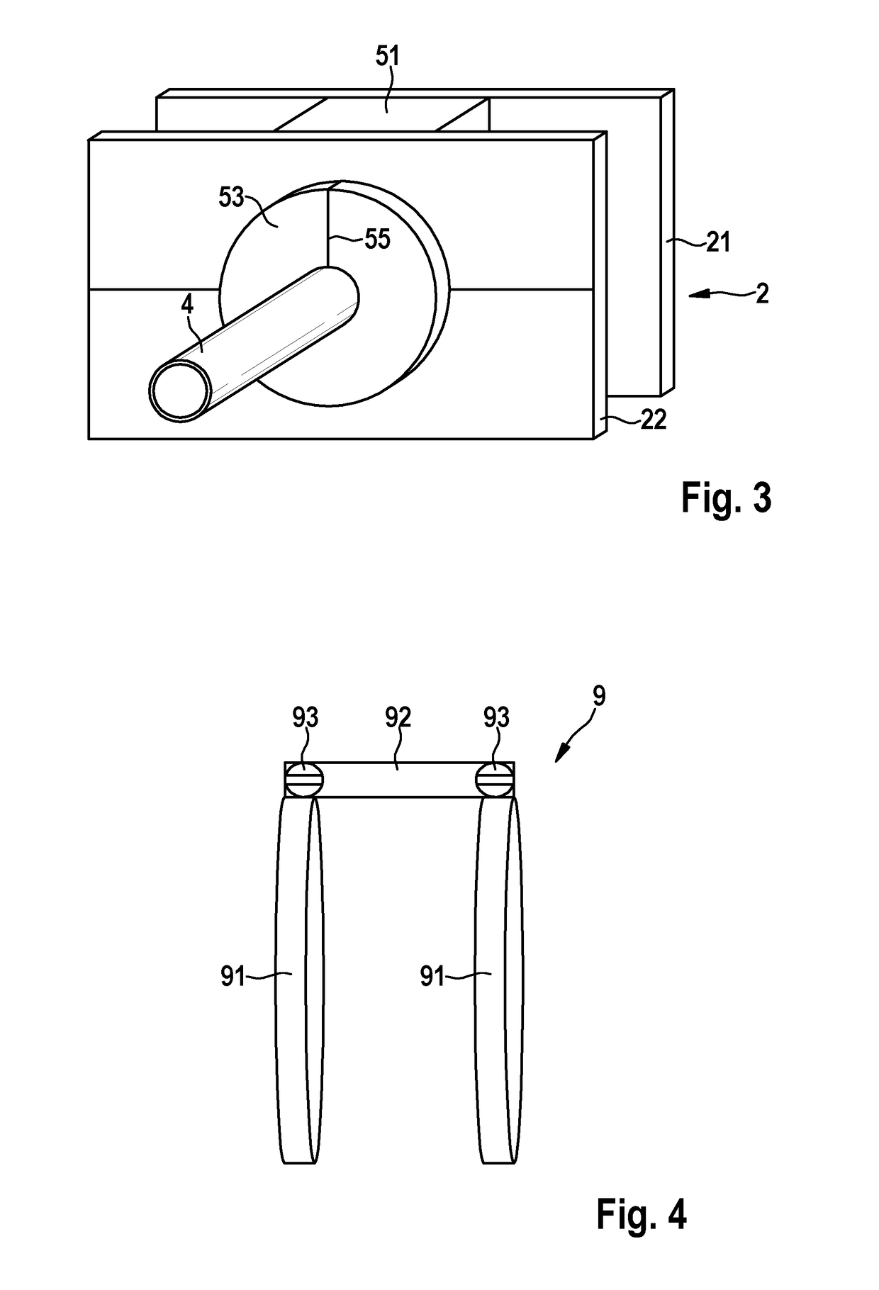
[0041]FIG. 1 schematically illustrates a cross-sectional diagram of a line penetration 1 through a building part 2, such as through a wall or ceiling of a building. FIG. 2 shows line penetration 1 without building part 2, and FIG. 3 shows a perspective diagram of line penetration 1 inserted into building part 2.

[0042]Building part 2 has a first building-part wall 21 and a second building-part wall 22, which are disposed opposite one another with a spacing and form an intermediate space Z. Building-part walls 21, 22 are preferably disposed with surfaces parallel to one another. As an example, such a building part 2 may be a drywall, wherein these building-part walls 2122 are frequently gypsum boards or the like.

[0043]Building-part walls 21, 22 have a first or a second wall opening 31 or 32, which are disposed opposite one another relative to intermediate space Z. A passage opening through building part 2 is formed by wall openings 31, 32. In the present exemplary embodiment, wall ope...


PUM


Abstract

A line penetration for routing a line through a passage opening of a building part that includes a first and a second building-part wall, between which an intermediate space is provided. The line penetration has a closure element that includes: an inner part for filling the intermediate space in the region of the passage opening; holding parts, with cross section smaller than that of the inner part, disposed on both sides of the inner part; a straight-through line opening, which penetrates the inner part and the holding parts in the direction in which they are disposed; and a sliding device, which is formed in order to guide the line slidingly and gas-tightly through the line opening.

Description

TECHNICAL FIELD[0001]The invention relates to a line penetration for routing a line through a building part, especially through a building wall or building ceiling. In particular, the present invention relates in general to fire-protection measures for routing lines through a building part.TECHNICAL BACKGROUND[0002]In buildings and installations, lines routed through a building part, such as a wall or a ceiling, for example, must satisfy fire-protection requirements. For example, one essential requirement is that combustion gases or even fire must not be permitted to penetrate the building part, i.e. must not be permitted to travel from one room in a building to the next.[0003]For this reason, it is customary, in the case of line penetrations through walls, to fill the intermediate space situated between the line and an inner wall of a passage opening with a flexible and rigid filling material, such as with mortar, PU bricks, acrylate sealing compound, mineral wool, especially in co...

Claims


Application Information

Patent Timeline
Patent Type & Authority Applications(United States)
IPC IPC(8): E04B1/94F16L5/04H02G3/04H02G3/22
CPCE04B1/947F16L5/04H02G3/0412H02G3/22H02G3/0481F16L5/025
Inventor WOLFGANG, SCHULZ-HANKEMUENZENBERGER, HERBERT
Owner HILTI AG
Why Eureka
Try Eureka