Automated molding machine for ultra small draft angle slurry molding products

a molding machine and ultra-small technology, applied in the field of automatic molding machines for ultra-small draft angle slurry molding products, can solve the problems of high recycling cost, serious damage to our environmental protection, and waste of plastic products

Active Publication Date: 2016-09-27
CHANGZHOU CHENGXIN ENVIRONMENTAL PROTECTION TECH CO LTD
View PDF26 Cites 3 Cited by
  • Summary
  • Abstract
  • Description
  • Claims
  • Application Information

AI Technical Summary

Benefits of technology

[0011]Therefore, it is a primary objective of the present invention to provide an automated molding machine for ultra small draft angle slurry molding products capable of moving the slurry suction die to a designated position and closing with the extrusion die precisely.
[0013]A further objective of the present invention is to provide an automated molding machine for ultra small draft angle slurry molding products with the effects of reducing the manufacturing time and labor, lowering the manufacturing cost, and improving the yield rate and the product competitiveness.
[0015]The automated molding machine for ultra small draft angle slurry molding products further comprises a front power cylinder and a rear power cylinder installed on a top surface of the top board. The front and rear power cylinders have cylinder shafts passing downwardly through the top board and then coupled to the front and rear action bases respectively. When the cylinder shafts of the front and rear power cylinders are extended or retracted synchronously, the front and rear action bases are driven to perform a descending or ascending action along the front and rear sides of the support column synchronously to achieve the effect of controlling the action frame to descend or ascend.
[0018]In the automated molding machine for ultra small draft angle slurry molding products, the extrusion die the extrusion die is coupled to a cylinder shaft of a power cylinder, and the power cylinder is installed at a top surface of the top board. The cylinder shaft of the power cylinder is passed downwardly through the top board and then coupled to the extrusion die to achieve the effect of controlling the extrusion die to descend or ascend.
[0020]In the automated molding machine for ultra small draft angle slurry molding products, the extrusion die includes a heater capable of providing a heating effect.

Problems solved by technology

Later studies show that plastic products may release toxins to cause severe pollution to the environment, and it is difficult to recycle, reuse or decompose plastic products, thus resulting in a high recycling cost.
Unfortunately, there is a huge amount of plastic products which has seriously damaged our environmental protection for years.
The conventional molding machine used for manufacturing the molding product has a major shortcoming that it is difficult to control the turnover action of the turning mechanism.
During the operation, a failure or an overturn may occur.
In addition, the up-and-down movements of the frame are driven by external power (which is generally from a power cylinder), and there is no other mechanism for righting or aligning in the stroke.
Thus, when the ascending or descending action reaches a fixed point, a deviation or a failure of aligning parallelly to the slurry suction die board may occur.
When the slurry suction die is driven to ascend and close with the extrusion die or driven to descend to close with the moving mold, an unmatched mold closing occurs frequently.
The frequent occurrence of unmatched mold closing results in a low yield rate, wastes manufacturing time and labor, and incurs a very high manufacturing cost.
In other words, for the conventional slurry suction die for each time of molding a blank, it is necessary to have a stroke of moving downwardly→upwardly→upwardly→downwardly, and thus wasting the manufacturing time and incurring a high manufacturing cost.

Method used


Image

  • Automated molding machine for ultra small draft angle slurry molding products
  • Automated molding machine for ultra small draft angle slurry molding products
  • Automated molding machine for ultra small draft angle slurry molding products

Examples


Embodiment Construction

[0026]The technical characteristics, contents, advantages and effects of the present invention will be apparent with the detailed description of preferred embodiments accompanied with related drawings as follows.

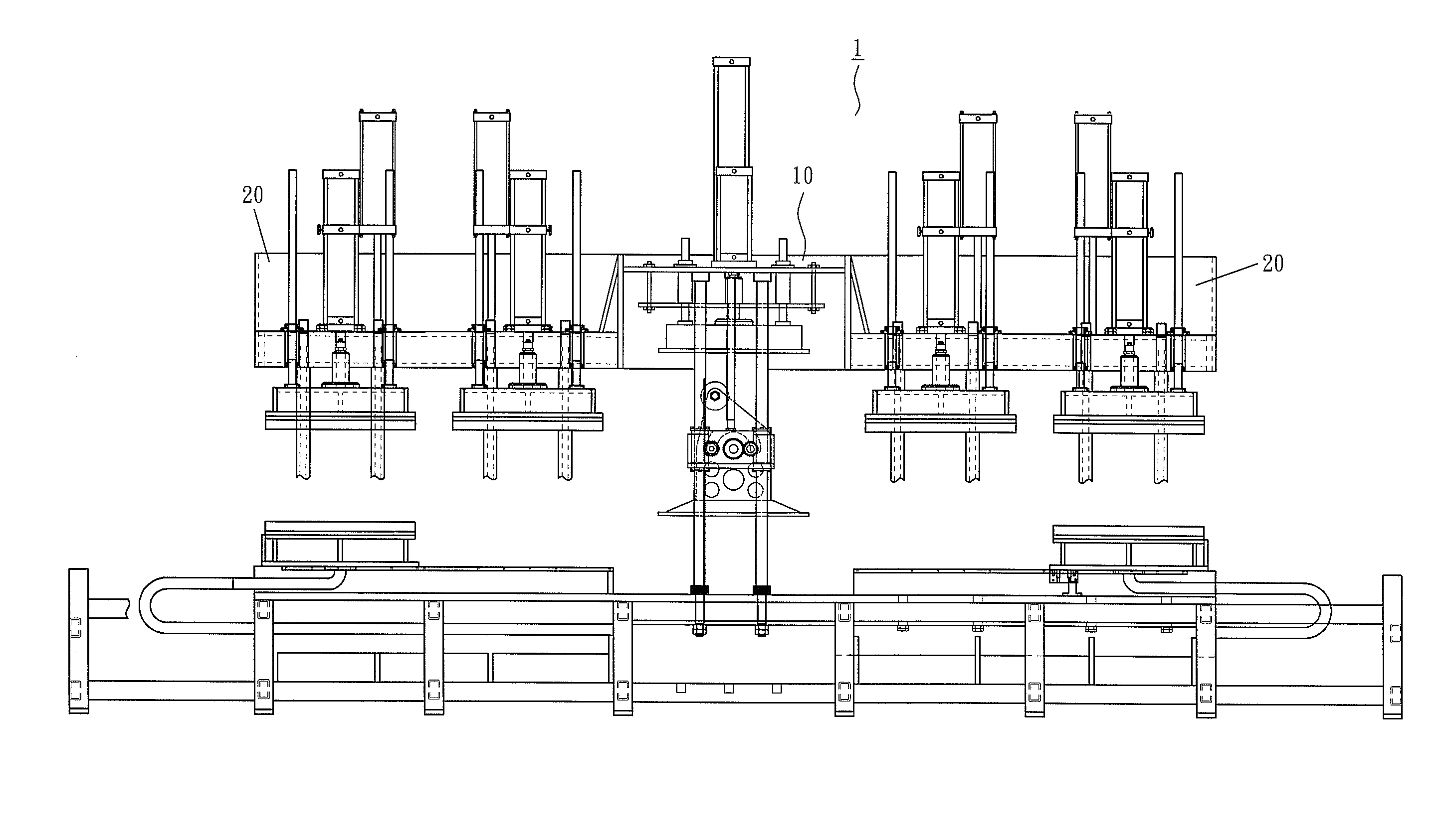
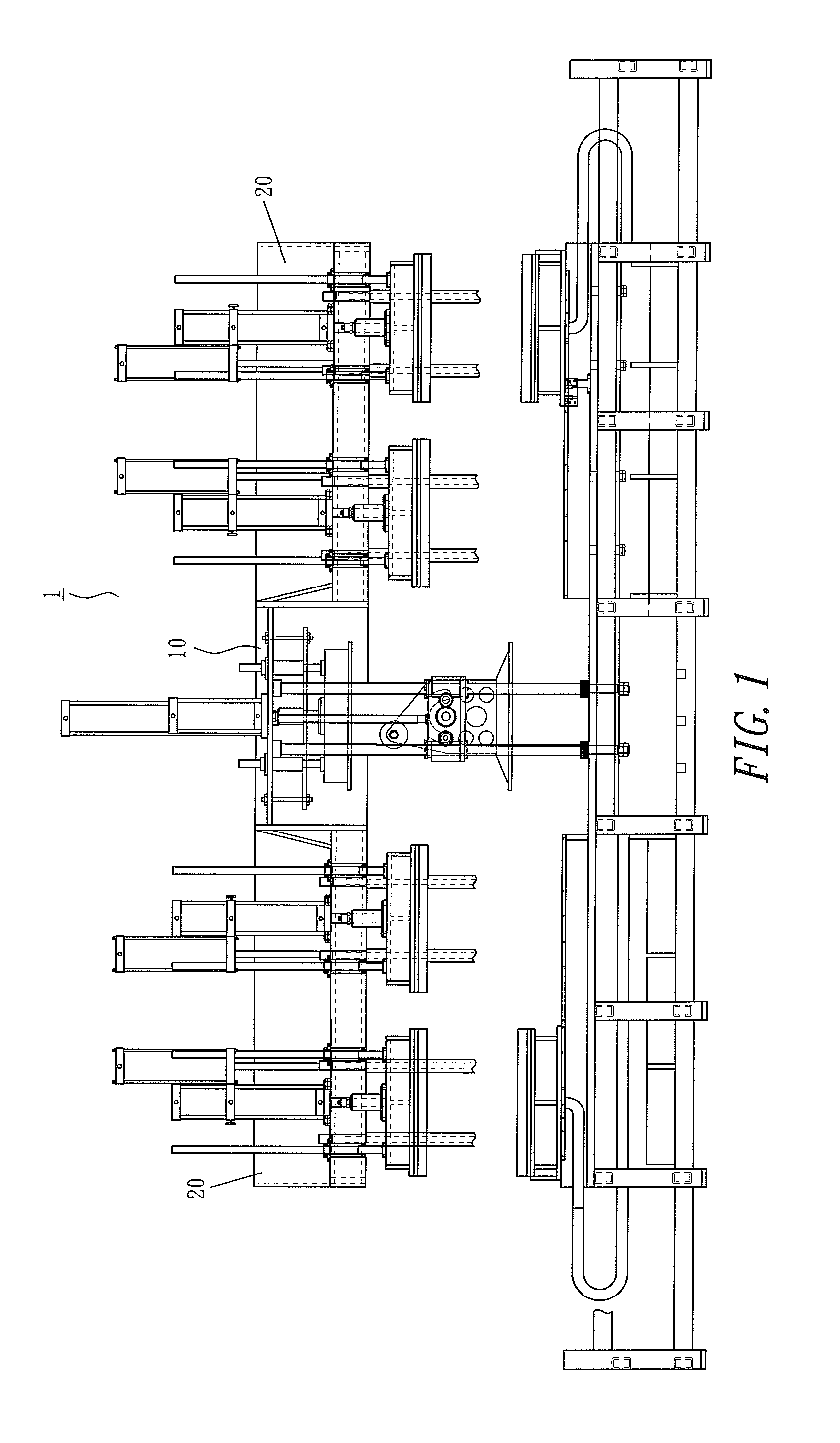
[0027]With reference to FIG. 1 for an automated molding machine 1 for manufacturing molding products in accordance with a preferred embodiment of the present invention, the molding machine 1 is specially applicable for manufacturing ultra small draft angle molding products, and the molding machine 1 comprises a main frame 10, a side frame 20 disposed separately on both sides of the main frame 10, and a means installed in the main frame 10 for performing a slurry suction molding process, and installed in a side frame 20 for performing a hot press truing process. In other words, blanks can be molded in the main frame 10 after the slurry suction molding process is completed, and then sent towards the right or left side into the side frame 20 sequentially for performing the hot ...


PUM

PropertyMeasurementUnit
distanceaaaaaaaaaa
forcesaaaaaaaaaa
weightaaaaaaaaaa

Abstract

In an automated molding machine for ultra small draft angle slurry molding products, a righting gear of a righting mechanism drives a turning mechanism to perform a turnover action to assist righting an ascending or descending action along a righting rack of a righting shaft synchronously. When a slurry suction die is moved up and down and / or turned over, the slurry suction die can be ascended to a designated position through the righting provided by the righting gear and the righting rack to achieve a precise closing when the slurry suction film is carried, ascended and closed with an extrusion die or descended and closed with a moving mold. Meanwhile, the extrusion die is controlled by a power cylinder to perform a descending stroke and close the mold with the slurry suction die.

Description

BACKGROUND OF THE INVENTION[0001]1. Field of the Invention[0002]The present invention relates to an automated molding machine for ultra small draft angle slurry molding products and, more particularly, to the automated molding machine for ultra small draft angle slurry molding products that descends an extrusion die to one stroke to match and mold with a slurry suction die, to achieve the effect of molding the slurry suction die with the extrusion die precisely at a designated position.[0003]2. Description of the Related Art[0004]At early stages, most industrial and household products were made of plastic. Later studies show that plastic products may release toxins to cause severe pollution to the environment, and it is difficult to recycle, reuse or decompose plastic products, thus resulting in a high recycling cost. Unfortunately, there is a huge amount of plastic products which has seriously damaged our environmental protection for years. In today's high level of environmental co...

Claims


Application Information

Patent Timeline
Patent Type & Authority Patents(United States)
IPC IPC(8): D21J3/00B28B1/26B29C41/16B31B50/00B31B50/59
CPCD21J3/00B28B1/261B28B1/265B29C41/16
Inventor LAI, TZUNG-SHENCHEN, JIAN-FANG
Owner CHANGZHOU CHENGXIN ENVIRONMENTAL PROTECTION TECH CO LTD
Why Eureka
Try Eureka