
Remaining-amount reduction member

a technology of remaining amount and member, which is applied in the direction of flexible containers, pliable tubular containers, packaging, etc., can solve the problem of content inevitably remaining in the space, and achieve the effect of stabilizing the amount of content ejection, reducing the cost of manufacturing, and achieving the desired mixture ratio

Active Publication Date: 2018-04-03
TOYO AEROSOL IND CO LTD
View PDF28 Cites 4 Cited by
  • Summary
  • Abstract
  • Description
  • Claims
  • Application Information

AI Technical Summary

Benefits of technology

[0032]According to the remaining-amount reduction member of the invention of claim 1, the guiding part has the plurality of grooved blocks connected in the longitudinal direction, each of the grooved blocks has one guiding groove in the longitudinal direction, and the guiding grooves form the guiding space continuing in the longitudinal direction. Thus, even when a remaining amount of a content reduces, the guiding grooves are opened on the side of an outer periphery at all parts in the longitudinal direction of the outer periphery and the guiding space continuing in the longitudinal direction functions as a path for causing the content to flow toward the inflow port. Therefore, the generation of space whose periphery is closed can be prevented over the entire length of the remaining-amount reduction member, and a final remaining amount of the content to be ejected can be reduced.
[0033]In addition, a sufficient flow amount can be secured to the end without depending on the status or material of the flexible interior bag since the guiding space continuing in the longitudinal direction can be caused to have a desired cross-sectional area. Therefore, it becomes possible to stabilize an ejection amount of the content per unit time, and becomes possible to reliably obtain a desired mixture ratio when a plurality of flexible interior bags is arranged in one exterior can.
[0034]Moreover, the adjacent grooved blocks are connected such that the openings of the guiding grooves thereof are oriented in the 180° opposite directions. Therefore, when the grooved blocks are manufactured using a die for injection molding or the like, it is possible to manufacture the grooved blocks using a two-split die. In addition, since the shape of the grooved blocks is simple, the manufacturing easiness and inexpensive costs of the grooved blocks are achieved.
[0035]According to the configuration of claim 2, each of the grooved blocks is formed to have an outer peripheral shape having an arc surface of over 180° and a groove forming surface, and each of the guiding grooves is formed to range from the groove forming surface in a direction toward an arc center and has a depth exceeding the arc center. Thus, the large openings of the guiding grooves and the guiding space having a large cross-sectional area can be secured while securing joining strength with respect to the adjacent grooved blocks. In addition, it becomes possible to reduce a final remaining amount of the content to be ejected and stabilize an ejection amount of the content with reduction in the resistance of a flow path.
[0036]According to the configuration of claim 3, the arc surface has an outer-surface groove, which extends in the longitudinal direction, at a position at which the outer-surface groove does not overlap with the arc surface of the adjacent grooved block. Thus, besides the central guiding space, a guiding path for the content is also formed on an outer-surface side by the outer-surface groove in the longitudinal direction. In addition, since the content smoothly flows in the inflow port, it becomes possible to stabilize an ejection amount of the content.
[0037]According to the configuration of claim 4, a connection neck part is provided between the attachment part and the grooved blocks, the connection neck part has an opening part opened on the side of the guiding groove of the adjacent grooved block and a 180° opposite side thereof, and the opening part communicates with the guiding space. Thus, it becomes possible to split the content, which flows from the guiding space toward the inflow port of the interior bag, into both sides of the attachment part. Therefore, since the content smoothly flows in the inflow port, it becomes possible to further stabilize an ejection amount of the content.

Problems solved by technology

In these aerosol containers, space whose periphery is closed by wrinkles or curves caused in an interior bag is generated when a remaining amount of a content to be ejected from the flexible interior bag reduces, whereby the content is caused to inevitably remain in the space to the end.

Method used


Image

  • Remaining-amount reduction member
  • Remaining-amount reduction member
  • Remaining-amount reduction member

Examples


first embodiment

[First Embodiment]

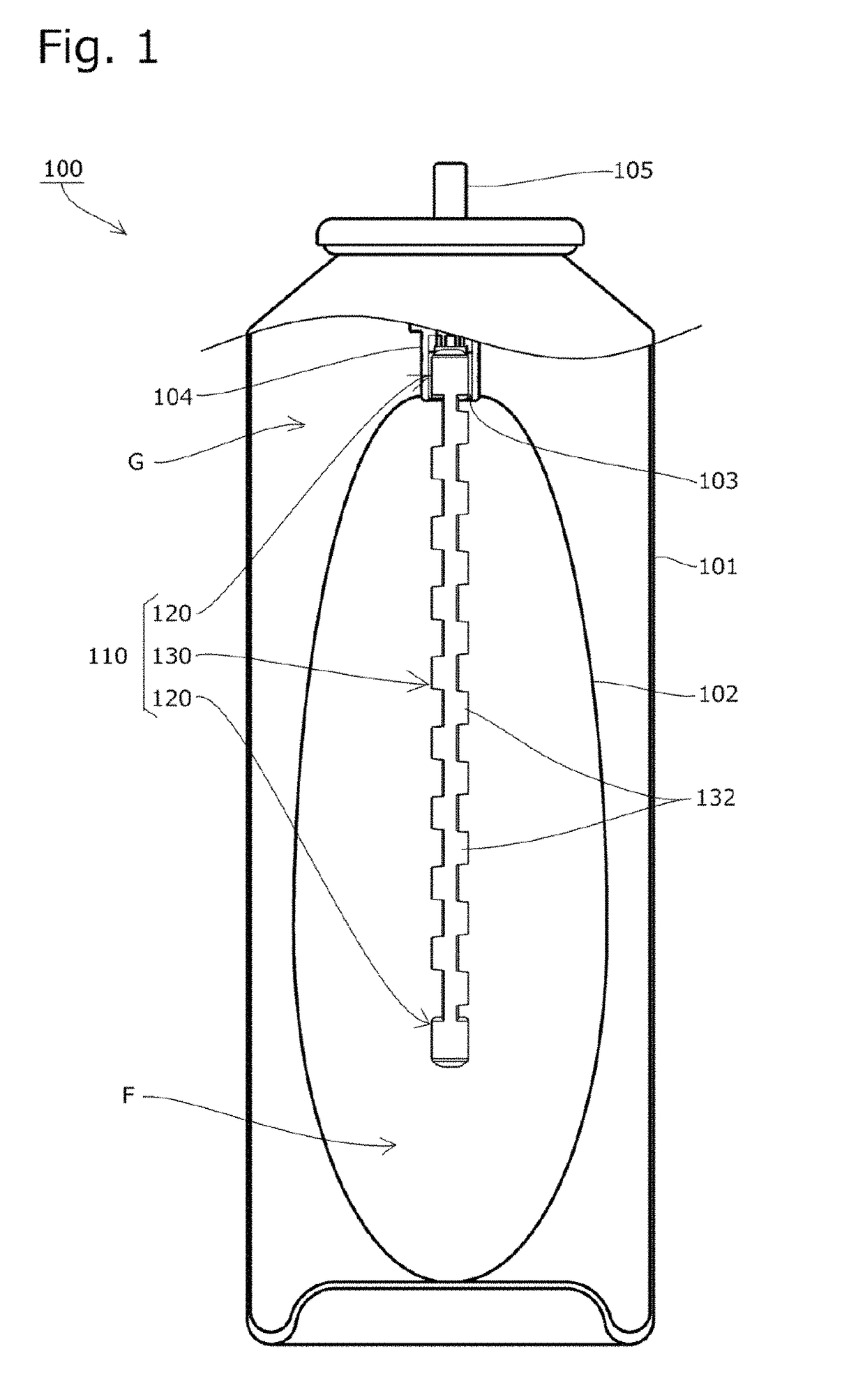
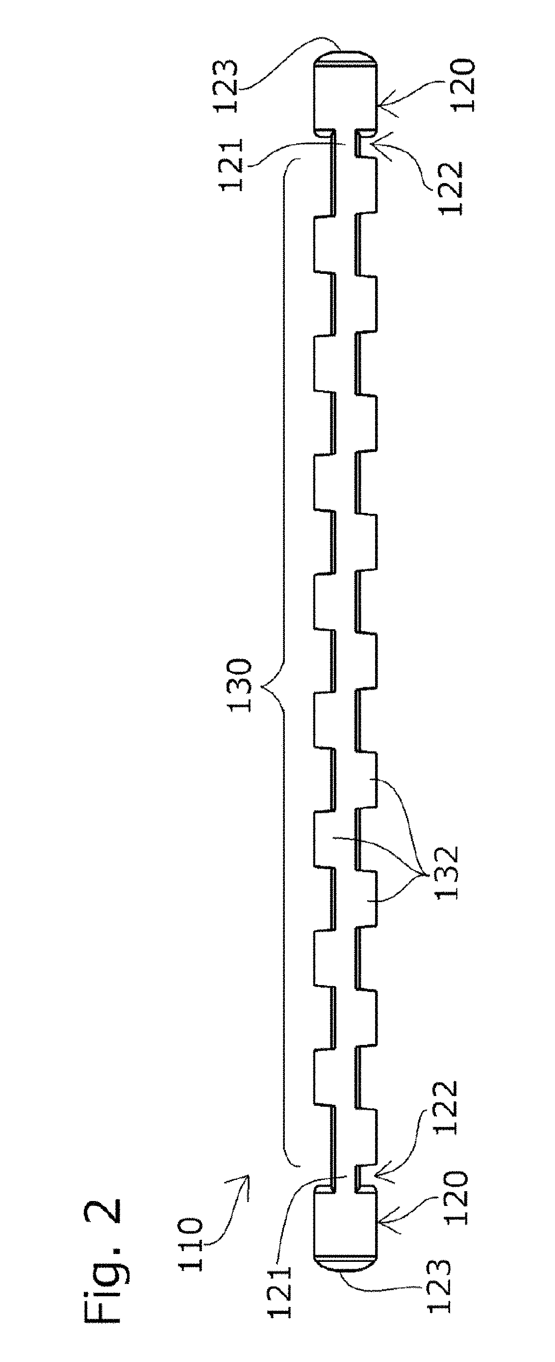
[0083]A remaining-amount reduction member 110 according to a first embodiment of the present invention is inserted in an inflow port 103 of an aerosol container 100 similar to the known aerosol container 500 described above instead of the known dip tube 511.

[0084]That is, as shown in FIG. 1, an interior bag 102 accommodating a content F is provided inside an exterior can 101 of the aerosol container 100, and the interior bag 102 is provided with a spout 104 having a stem 105 at its upper part and the inflow port 103 opened inside the spout 104.

[0085]The space between the exterior can 101 and the interior bag 102 of the aerosol container 100 is filled with pressurized fluid G such as nitrogen gas. When the stem 105 is pressed, the content accommodated in the interior bag 102 is configured to flow in the inflow port 103 to be ejected to an outside from the tip of the stem 105.

[0086]Further, in the inflow port 103 of the interior bag 102, the remaining-amount reductio...

second embodiment

[Second Embodiment]

[0112]As shown in FIG. 9 to FIG. 12, a remaining-amount reduction member 210 according to a second embodiment of the present invention has, besides the configuration of the remaining-amount reduction member 110 according to the first embodiment described above, a configuration in which arc surfaces 233 have two respective outer-surface grooves 238 extending in the longitudinal direction at their positions at which the outer-surface grooves 238 do not overlap with the arc surfaces 233 of adjacent grooved blocks 232 in the longitudinal direction (the same constituents as those of the first embodiment are shown in the figures by corresponding reference signs in the 200s and their descriptions will be omitted).

[0113]As shown in FIG. 12B, the outer-surface grooves 238 are provided at the two spots of the arc surface 233 of each of the grooved blocks 232 so as to extend in the longitudinal direction.

[0114]In the embodiment, the outer-surface grooves are formed at exact ...


PUM


Abstract

An object of the present invention is to provide a remaining-amount reduction member capable of preventing the generation of space whose periphery is closed by pressurized fluid, reducing a final remaining amount of a content to be ejected, stabilizing an ejection amount of the content per unit time, and smoothly ejecting the content to the end.Provided is a remaining-amount reduction member 110 that is attached inside a flexible interior bag 102 arranged inside an aerosol container 100, the remaining-amount reduction member including: an attachment part 120 attached such that the content F is capable of flowing in an inflow port 103 of the interior bag 102; and a guiding part 130 having a plurality of grooved blocks 132, each of which has a guiding groove 131 in a longitudinal direction, connected in the longitudinal direction.

Description

TECHNICAL FIELD[0001]The present invention relates to a remaining-amount reduction member that is attached inside a flexible interior bag arranged inside an aerosol container and used to reduce a final remaining amount of a content to be ejected.BACKGROUND ART[0002]There have been known aerosol containers configured to have a flexible interior bag arranged and integrated inside an exterior can, accommodate a content to be ejected in the interior bag, and fill the space between the interior bag and the exterior can with pressurized fluid to press the flexible interior bag and eject the content accommodated in the interior bag to an outside via an inflow port (see, for example, PTL 1 or the like).[0003]In such aerosol containers, it is possible to use any pressurized fluid since a content does not contact the pressurized fluid. In addition, the content can be efficiently ejected since pressurized fluid is not ejected together with the content.[0004]In these aerosol containers, space w...

Claims


Application Information

Patent Timeline
Patent Type & Authority Patents(United States)
IPC IPC(8): B65D35/56B65D83/68B65D83/62B65D83/32
CPCB65D83/32B65D83/68B65D83/62B65D1/323
Inventor OGATA, KEN
Owner TOYO AEROSOL IND CO LTD
Learn More