Optical fiber penetration

a technology of optical fiber and penetration, applied in the field of optical fiber penetration, can solve the problems of inability to use radiation-resistant fibers as penetration, inability to penetrate optical fibers, and easy breakage of fiber strands alone,

Active Publication Date: 2018-04-03
ORIENT BRAINS
View PDF11 Cites 0 Cited by
  • Summary
  • Abstract
  • Description
  • Claims
  • Application Information

AI Technical Summary

Benefits of technology

[0019]According to an optical fiber penetration and a system of the present invention, while the optical fiber of the first cable and an optical fiber of the second cable are electrically connected with each other, the connector ensures airtightness of each of the cables to prevent intrusion of radiation rays, heat, and water, thereby protecting the optical fibers.

Problems solved by technology

Due to an issue of radiation resistance of optical fibers, optical fibers have not been used in Japan for transmitting the measured data of temperatures and the water levels in the nuclear reactor containments.
However, the radiation-resistant fibers as they are cannot be used as a penetration, since resin coating thereof lacks heat resistance and pressure resistance, and in addition, a fiber strand alone is easy to break and lacks durability.

Method used


Image

  • Optical fiber penetration
  • Optical fiber penetration
  • Optical fiber penetration

Examples


Embodiment Construction

[0027]An Embodiment of the present invention is described below with reference to the drawings.

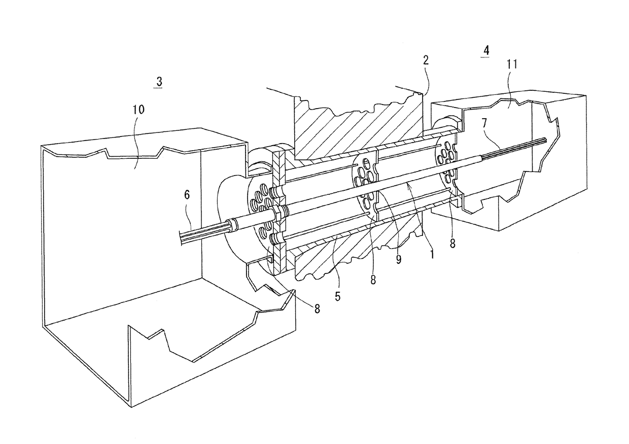
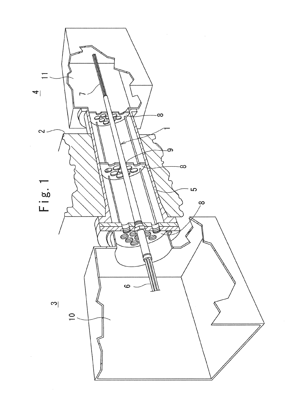
[0028]Referring to FIG. 1, an optical fiber penetration 1 according to the embodiment is placed in a cylindrical sleeve 5 penetrating a partition wall 2 of a nuclear reactor containment to communicate an inner space (first space) 3 of the containment on the left side in FIG. 1 (inside of the partition wall 2) and an outer space (second space) 4 of the containment on the right side in FIG. 1 (outside of the partition wall 2) with each other. Note that a part of each component toward the inside of the nuclear reactor containment and a part of each component toward the outside of the nuclear reactor containment are simply indicated by using the terms “inner” and “outer” respectively in the present specification for the purpose of convenience.

[0029]The optical fiber penetration 1 joins inner optical fiber cables 6, which are connected with a sensor (not shown) disposed in the inner space 3 of ...


PUM


Abstract

An optical fiber penetration is disposed in a sleeve provided through a partition wall that separates a first space and a second space. The optical fiber penetration includes a first optical fiber cable and a second optical fiber cable each having a thin tube formed of metal and an optical fiber strand inserted in the thin tube, a cylindrical body that is formed of metal and is disposed in an axial direction of the sleeve, an interior of which includes the first optical fiber cable on a side of the first space and the second optical fiber cable on a side of the second space, an internal connector configured to connect the first optical fiber cable with the second optical fiber cable in the interior of the cylindrical body, and a first lid and a second lid configured to close one end and the other end of the cylindrical body.

Description

TECHNICAL FIELD[0001]The present invention relates to an optical fiber penetration configured to penetrate a partition wall provided in a container, a facility, or a room such as a nuclear reactor containment, a shelter, a safe, an airtight area of a chemical plant, which requires separation between inside and outside thereof in order to connect cables extending the inside and the outside of the partition wall.BACKGROUND ART[0002]Patent document 1 discloses a conventional penetration in which: a header ring is provided through an adaptor on an external end of a sleeve which penetrates a shielding wall of a nuclear reactor containment; a plurality of cable modules are mounted on the header ring; outside cables of the cable modules are connected with external cables through terminal parts; and inside cables of the cable modules are connected with internal cables through terminal parts. When such a penetration is in need of replacement, a welded part between the adaptor and the sleeve ...

Claims


Application Information

Patent Timeline
Patent Type & Authority Patents(United States)
IPC IPC(8): G02B6/38G02B6/46G21C13/036G02B6/44
CPCG02B6/3816G02B6/3893G21C13/036G02B6/46G02B6/443G21D1/00G02B6/4428G02B6/3869Y02E30/30Y02E30/00
Inventor MINAMIDE, KOJIMINAMIDE, DAISUKE
Owner ORIENT BRAINS
Why Eureka
Try Eureka