
Pneumatic fastening for fastening a surface paneling to an aircraft surface

a technology of surface paneling and pneumatic fastening, which is applied in the direction of fuselage, ground installation, fuselage frame, etc., can solve the problems of preloading the panel into undesirable levels, wear and loosening of the fastener, and potentially hazardous conditions with respect to mechanical and electrical systems in the vicinity

Active Publication Date: 2018-04-10
NORTHROP GRUMMAN SYST CORP
View PDF5 Cites 0 Cited by
  • Summary
  • Abstract
  • Description
  • Claims
  • Application Information

AI Technical Summary

Benefits of technology

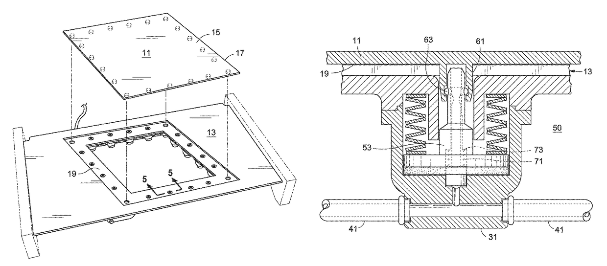
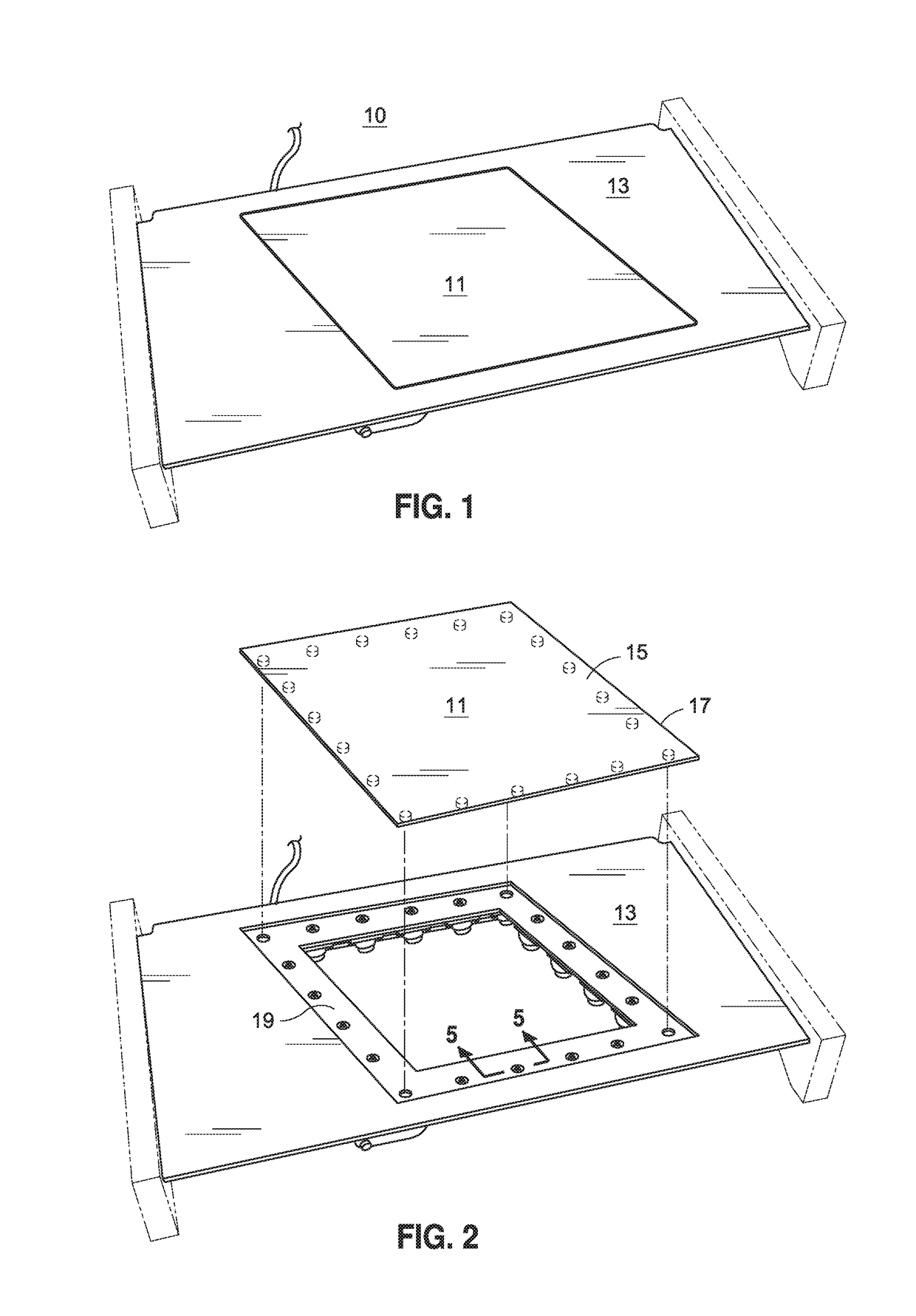
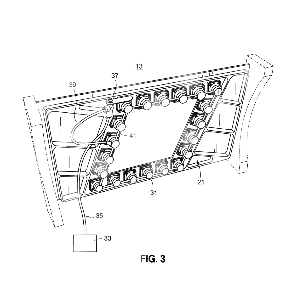
The present invention is for a mechanism for fastening an aircraft surface panel to an aircraft panel support member using a pneumatic fastening system. The mechanism includes engagement mechanisms on the support member and receptacles on the panel that can lock onto the engagement mechanisms to secure the panel in place. The engagement mechanisms can elevate the panel to a position above the support member for unlocking and separation from the panel. The mechanism is operative to elevate and release the panel by changing the fluid pressure communicated to the engagement mechanisms. The mechanism uses plunger mechanisms that can translate to lock or release the panel from the support member. The plungers can be caused to extend and retract to secure or release the panel. The mechanism is simple, efficient, and effective for fastening aircraft panel to the support member.

Problems solved by technology

While panels may be conventionally engaged to an aircraft surface by means of screws or similar fasteners, such connecting means commonly require torqueing the fasteners to a desired pressure, can result in wear and loosening of the fasteners during use, and can preload the panels into undesirable levels.
Moreover, in practical circumstances of use, fasteners can fall into the aircraft interior when installing or removing the panel, creating potentially hazardous conditions with respect to mechanical and electrical systems disposed in the vicinity.

Method used


Image

  • Pneumatic fastening for fastening a surface paneling to an aircraft surface
  • Pneumatic fastening for fastening a surface paneling to an aircraft surface
  • Pneumatic fastening for fastening a surface paneling to an aircraft surface

Examples


Embodiment Construction

[0020]The detailed description below is given by way of example, and not limitation. Given the disclosure, one skilled in the art could devise variations that are within the scope and spirit of the invention disclosed herein. Further, the various features of the embodiments disclosed herein can be used alone, or in varying combinations with each other and are not intended to be limited to the specific combination described herein. Thus, the scope of the claims is not to be limited by the illustrated embodiments.

[0021]FIG. 1 is a perspective view of the pneumatic fastening mechanism 10, showing aircraft panel 11 in place on panel support member 13. As described above, the aircraft panel 11 may be removed from the panel support member 13, to allow access to aircraft electronic, mechanical or pneumatic systems disposed below the panel 11. Moreover, as described above, it is desirable that the panel 11 does not include any handles or fasteners that might negatively effect the aerodynami...


PUM


Abstract

A pneumatic fastening mechanism is provided for fastening an aircraft surface panel to an aircraft panel support member. The panel includes a plurality of receptacles extending from the panel lower surface. The panel support member includes a corresponding plurality of panel engagement mechanisms, disposed on the support member lower surface, and translatable through the support member to engage the receptacles. The panel engagement mechanisms are extendable from a first position, wherein the panel abuts and is engaged to the panel support member, to second position wherein the panel is elevated above the panel support member upper surface where the panel may be unlocked and separated from the panel engagement mechanism. The panel engagement mechanism is operative to elevate and release the panel in response to changes in fluid pressure communicated to the panel engagement mechanisms.

Description

STATEMENT RE: FEDERALLY SPONSORED RESEARCH / DEVELOPMENT[0001]Not ApplicableBACKGROUND[0002]The present invention relates to a latching mechanism that allows a removable access panel to separate from a supporting surface when access to the aircraft interior is desired. More particularly, the present invention relates to a latching mechanism suitable for rapid removal and reinstallation of aircraft outer mold line (OML) panels and doors.[0003]In the building of aircraft, both civil and military, exterior panels, doors and other structures are provided which can be removed for repair or to allow access to aircraft systems, e.g. mechanical, electrical or hydraulic, disposed within the body of the aircraft. The panel doors are preferably formed flush with the adjacent aircraft surface, to avoid interference with aerodynamic characteristics of the aircraft. Irregularities in an aircraft surface can also mitigate low observable characteristics of an aircraft, as RF signals may reflect from ...

Claims


Application Information

Patent Timeline
Patent Type & Authority Patents(United States)
IPC IPC(8): B64C1/06B64C1/12B64F5/00
CPCB64C1/12B64F5/0009B64C1/1446
Inventor COMBS, CORY M.SMITH, CHARLESRUFINO, JOHNNOERTKER, KEVIN A.CIFU, GREG A.
Owner NORTHROP GRUMMAN SYST CORP
Learn More