Method and system for gasflow management

a gasflow management and gas flow technology, applied in the field of fuel cells, can solve problems such as safety concerns and system instability

Inactive Publication Date: 2013-11-14
M FIELD ENERGY
View PDF1 Cites 0 Cited by
  • Summary
  • Abstract
  • Description
  • Claims
  • Application Information

AI Technical Summary

Benefits of technology

[0005]An gasflow management system comprises an input terminal to receive an input source with an input pressure level, a pressure-reducing valve to reduce the input pressure level to a reduced pressure level, a connector to connect the pressure-reducing valve to a release valve, a pressure sensor, and an output terminal, whereas the release valve is adapted to release a part of the input source if a first condition is met, and the pressure sensor is adapted to sense an output pressure level. In addition, the gasflow management system may further comprise a switch valve with a first state and a second state, wherein the input source may reach the pressure-reducing valve when the switch valve operates at the first state and the input source may not reach the pressure-reducing valve when the switch valve operates at the second state.

Problems solved by technology

In addition, if the hydrogen pressure is outside of the safety range, the system may become unstable and may raise safety concerns.

Method used


Image

  • Method and system for gasflow management
  • Method and system for gasflow management
  • Method and system for gasflow management

Examples


Embodiment Construction

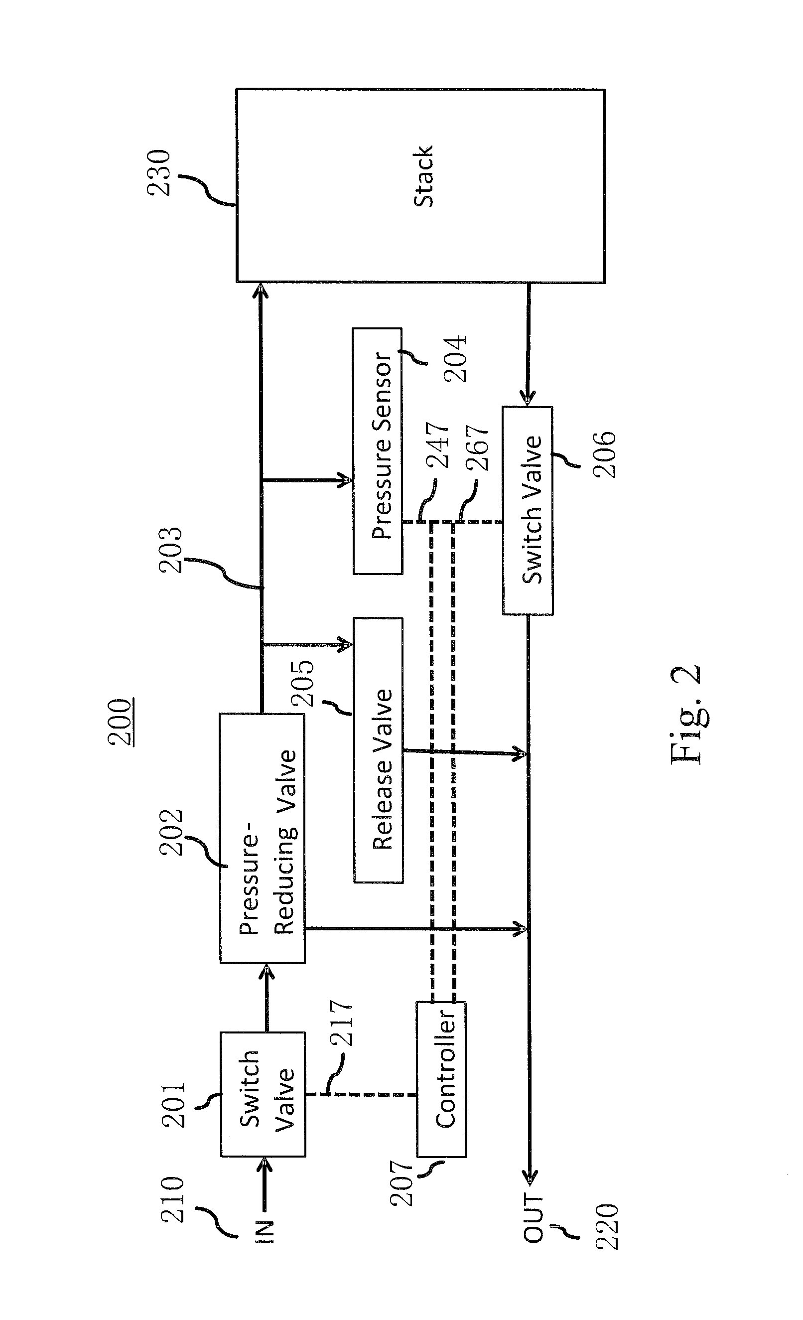
[0010]Embodiments of the present invention provide an gasflow management system that provides a safety module to ensure that the gasflow pressure remains within a pre-specified range inside the fuel cell system.

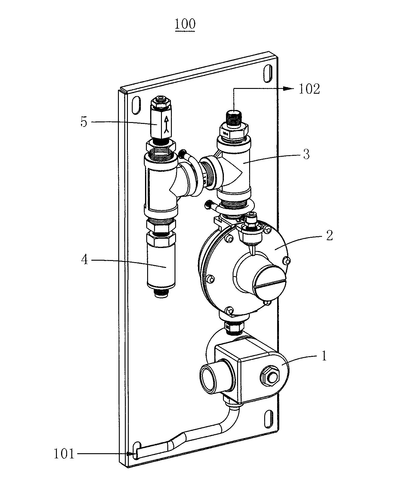
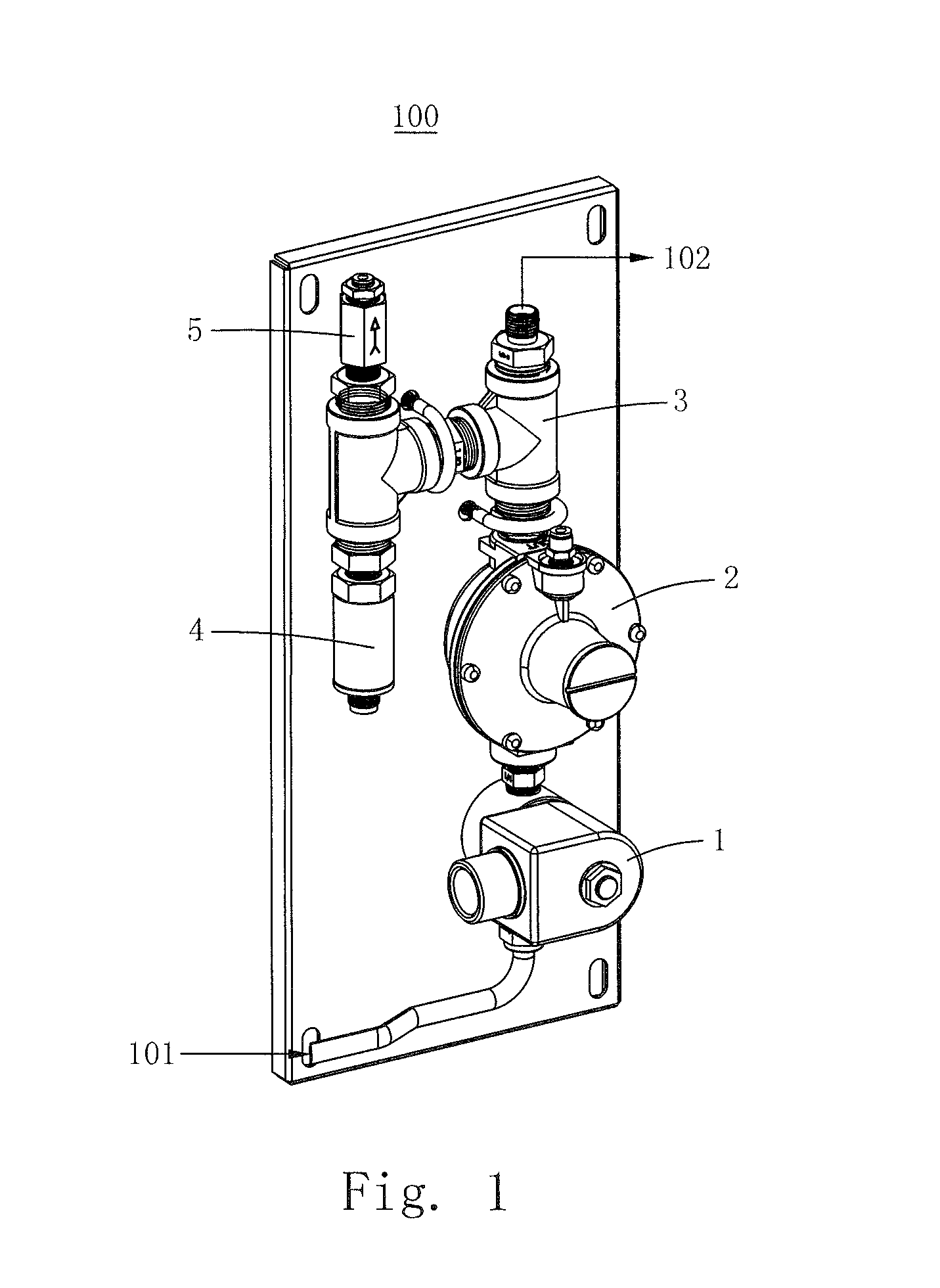
[0011]FIG. 1 is a simplified diagram illustrating components of an exemplary gasflow management system. As shown, the gasflow management system 100 may receive an input source from the input terminal 101. The input source may be the fuel used in a fuel cell system. For example, the input source may be hydrogen or oxygen. Once the input source enters the gasflow management system 100, it may pass the switch valve 1. In one embodiment of the present invention, the pressure of the input source at the input terminal 101 (“the system input pressure”) is higher than the required operating pressure, which may be the pressure at the output terminal 102 (“the system output pressure”). Having the system input pressure higher than the system output pressure may facilitate the storage of...


PUM


Abstract

A system and method for gasflow management to ensure that the output pressure is within a safety range. Upon entering the input terminal, the input source may pass through a switch valve to reach a pressure-reducing valve so that the pressure is reduced to a reduced pressure level. Then, the reduced pressure level is checked by the release valve and is lowered if the reduced pressure level is higher than the cutoff pressure associated with the release valve. The reduced pressure level is also sensed by a pressure sensor so that the controller can shut off the operation if the pressure reading is not within a safety range.

Description

BACKGROUND[0001]Aspects of the present invention relate generally to the field of fuel cell, and more specifically to the gas flow control mechanism used by the fuel cell system.[0002]A typical fuel cell system has an anode, the electrolyte, and a cathode, whereas the electrolyte is sandwiched between the anode and cathode. When a catalyst oxidizes the fuel at the anode, the fuel is transformed into a positively charged ion and a negatively charged electron. Then, the negatively charged electron causes electric current by passing through a load circuitry, while the positively charged ion passes through the electrolyte to reach the cathode. At the cathode, the positively charged ion can unite with the negatively charged electron and react with another chemical. Usually, the fuel is hydrogen and the chemical at the cathode is oxygen.[0003]To ensure that the fuel cell operates efficiently, the flow of hydrogen must be maintained. In addition, if the hydrogen pressure is outside of the ...

Claims


Application Information

Patent Timeline
Patent Type & Authority Applications(United States)
IPC IPC(8): F16K21/04
CPCF16K21/04H01M8/2465H01M8/04089Y10T137/0324Y10T137/7793Y02E60/50
Inventor HSU, CHIH PIN
Owner M FIELD ENERGY
Why Eureka
Try Eureka