Engine systems and methods

Active Publication Date: 2019-08-08
GENERAL ELECTRIC CO
View PDF2 Cites 0 Cited by
  • Summary
  • Abstract
  • Description
  • Claims
  • Application Information

AI Technical Summary

Benefits of technology

[0006]In one embodiment, an airfoil is configured to be disposed inside of an engine assembly including a fan frame assembly. The airfoil is shaped to direct air inside the engine assembly. The airfoil includes a pressure side and a suction side that are coupled together at a leading edge of the airfoil and that are coupled together at a trailing edge of the airfoil that is located downstream from the leading edge. The airfoil extends a radial length away from a central axis of the engine assembly between a hub end of the airfoil and an opposite tip end of the airfoil. The leading edge of the airfoil includes a sweep feature that is shaped to alter the a

Problems solved by technology

Rotating fan blades of the fan assembly generate air wakes that interfere with outlet guide vanes downstream from the fan blades.
Additionally, the air wake interferes with the outlet guide vanes to generate aerodynamic noise.
Such aerodynamic noise may be seen as a nuisance or discomfort to aircraft passengers, or may exceed a

Method used


Image

  • Engine systems and methods
  • Engine systems and methods
  • Engine systems and methods

Examples


Embodiment Construction

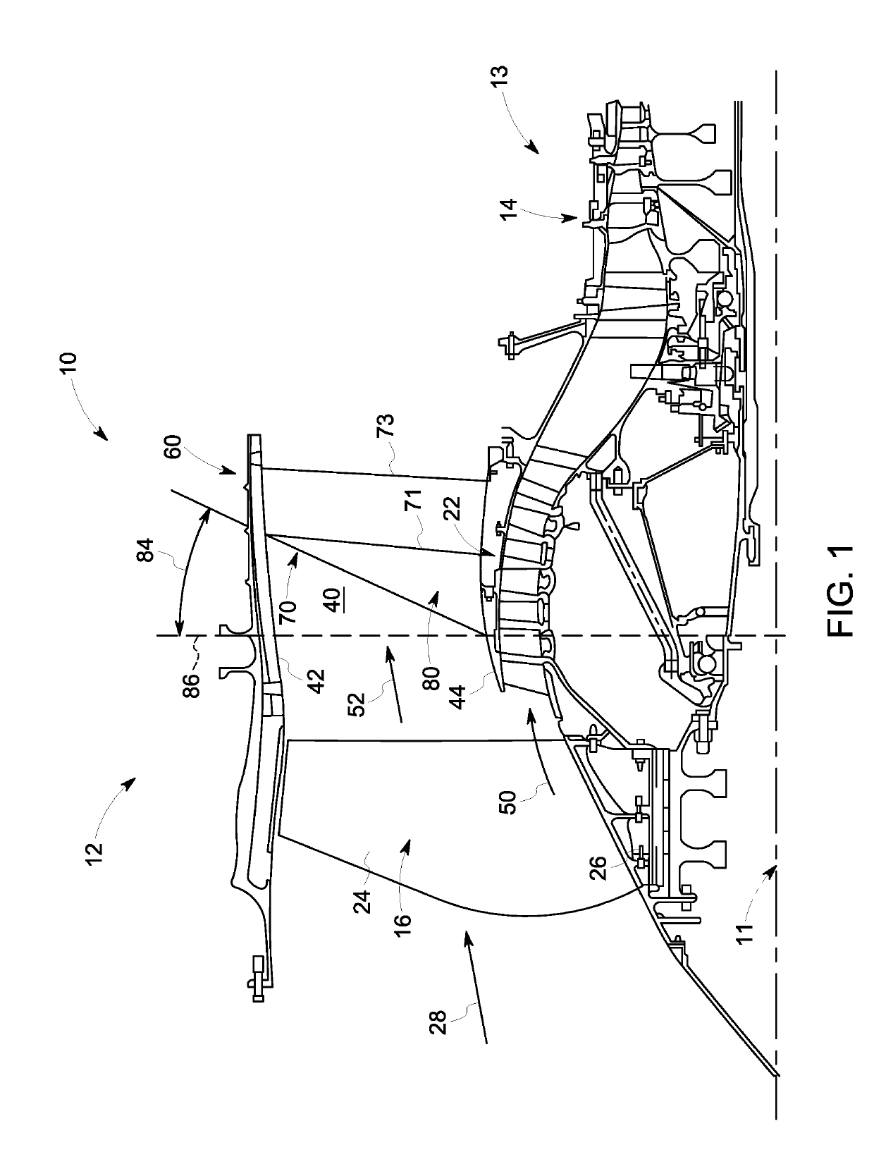
[0015]One or more embodiments of the inventive subject matter described herein relates to systems and methods that include an airfoil that is integrated with a fan frame assembly disposed inside of an engine assembly. Integrating the airfoil with the fan frame assembly improves a structural load supporting capability of the fan frame assembly relative to the airfoil not being integrated with the fan frame assembly. Additionally, a sweep feature can be provided at a leading edge of the airfoil that alters the air inside the engine assembly. Altering the air flow inside the engine assembly with the sweep feature improves the reduction of an amount of surface pressure exerted on the airfoil by the air and reduces the noise generated by the engine assembly relative to the leading edge of the airfoil not including the sweep feature.

[0016]FIG. 1 illustrates a partial cross-sectional view of a gas turbine engine assembly 12 in accordance with one embodiment. The gas turbine engine assembly...


PUM


Abstract

A system includes an airfoil disposed inside an engine assembly that includes a pressure side and a suction side that are coupled together at a leading edge and a trailing edge. The airfoil extends a radial length away from a central axis of the engine assembly between a hub end and a tip end. The airfoil includes a sweep feature disposed at the leading edge that is shaped to alter the air inside the engine assembly. Altering the air inside the engine assembly reduces a surface unsteady pressure level on the airfoil. The system includes a fan frame assembly comprising an inner and outer surface. The hub end is coupled with the inner surface and the tip end is coupled with the outer surface. The airfoil is integrated with the fan frame assembly such that the airfoil increases a structural load supporting capability of the fan frame assembly.

Description

FIELD[0001]The subject matter described herein relates to aircraft systems.BACKGROUND[0002]During operation of a gas turbine engine assembly, airflow is channeled from a fan assembly to a fan stream exhaust. Rotating fan blades of the fan assembly generate air wakes that interfere with outlet guide vanes downstream from the fan blades. The outlet guide vanes may reduce an amount of swirl that is present in the air wake by turning the flow of air from the fan. Additionally, the air wake interferes with the outlet guide vanes to generate aerodynamic noise. Such aerodynamic noise may be seen as a nuisance or discomfort to aircraft passengers, or may exceed a noise ordinance law or requirement.[0003]In addition to turning the fan airflow, the outlet guide vanes may also provide structural stiffness to the fan frame. More specifically, the outlet guide vanes may be integrated with the fan frame, forming an integrated fan frame assembly.[0004]Known systems for reducing an amount of aerody...

Claims


Application Information

Patent Timeline
IPC IPC(8): F04D29/54F04D29/66
CPCF04D29/544F04D29/667F02C3/04F05D2220/323F05D2230/80F05D2240/121F05D2240/122F05D2260/96F02C7/045F04D29/541F05D2220/36F01D25/162F01D9/041F01D9/042
Inventor WOOD, TREVORRAMAKRISHNAN, KISHORE
Owner GENERAL ELECTRIC CO
Why Eureka
Try Eureka