Pressing device

Inactive Publication Date: 2010-05-25
VOITH PATENT GMBH
View PDF28 Cites 1 Cited by
  • Summary
  • Abstract
  • Description
  • Claims
  • Application Information

AI Technical Summary

Benefits of technology

[0008]On account of this embodiment, a relatively uniform pressure distribution is possible in the machine running direction and transverse direction, with the result that pressure profiles which are as planar as possible can be produced. This therefore results in a relatively large pressing surface which faces the pressure shoe or its lower part, which results in the pressure which is required to achieve the necessary line force can be kept relatively low. In comparison with pressing using individual pistons, lower pressure levels of the pressure fluid are possible.
[0035]According to a further refinement of the invention, the pressure shoe can be mounted rotatably in the machine running direction, to be precise, in particular, centrally. Moreover, the pressure shoe can also be mounted in the machine transverse direction, in particular in a multiple manner. This has the advantage that a defined position of the pressure shoe results, without stop bars being required. As a result, the pressure shoe is given a position which can be calculated exactly, and the pressure profile can also be calculated exactly. Furthermore, the rotatable mounting can for its part be mounted so as to move freely in the horizontal direction.

Problems solved by technology

However, an oil pressure bed causes problems, in particular, with regard to sealing.
The use of separate pressing pistons is associated with the disadvantage of a deviation in the transverse pressure profile which is caused by the individual pistons.

Method used


Image

  • Pressing device
  • Pressing device
  • Pressing device

Examples


Embodiment Construction

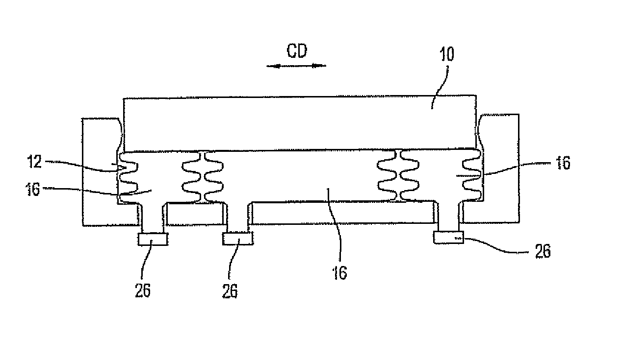
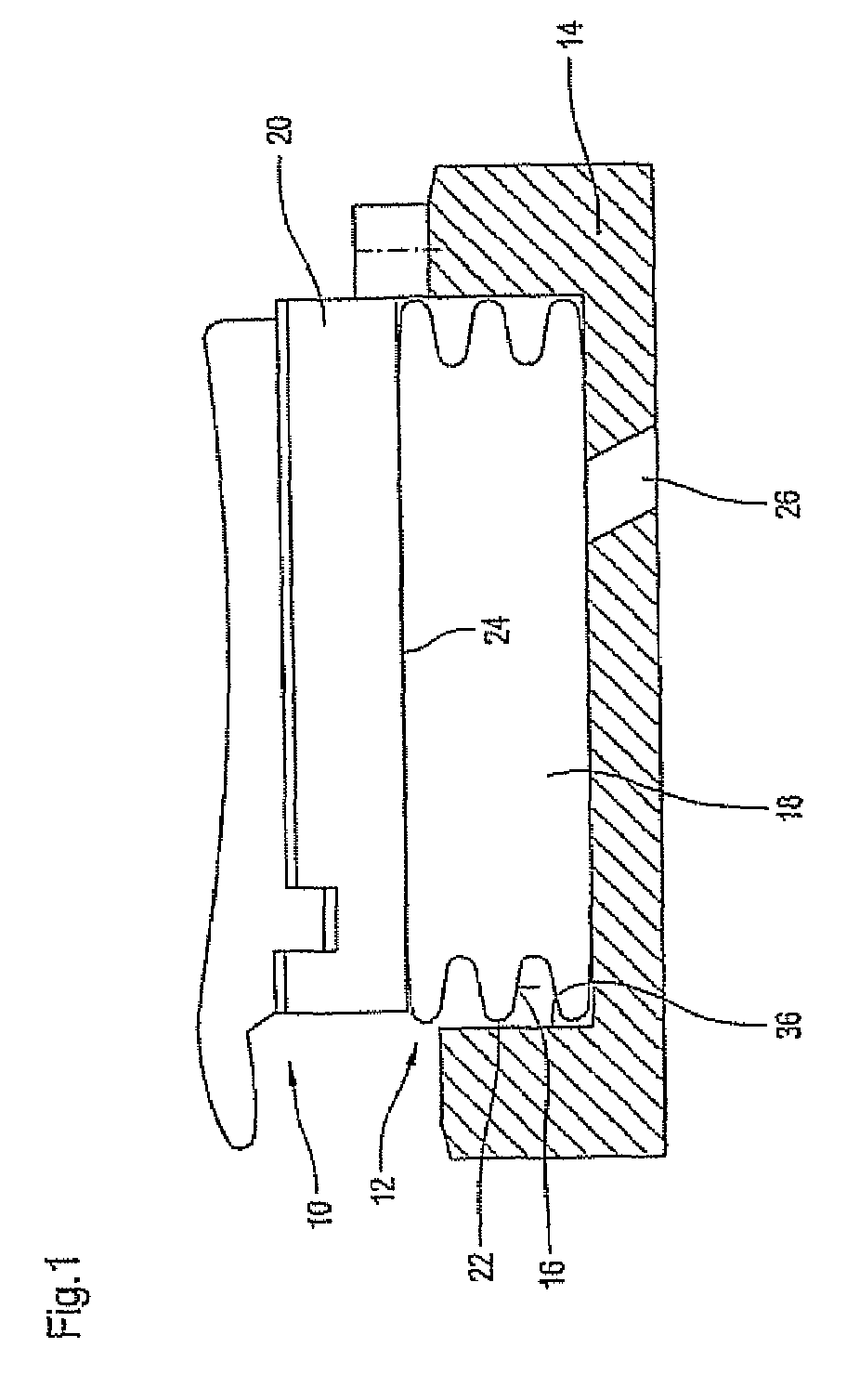
[0047]In a diagrammatic cross-sectional illustration, FIG. 1 shows a pressure shoe 10 having an associated pressing device 12.

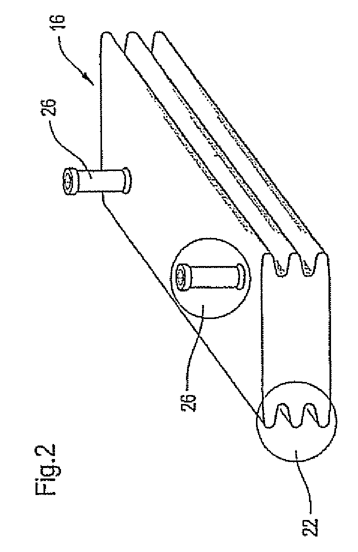
[0048]The pressing device 12 comprises at least one pressure element 16 which is supported on a supporting body 14 and is flexible at least in regions. The pressure element 16 has at least one hollow space 18 which can be acted on with pressure fluid, in order to produce a predefinable pressing force via a corresponding pressure element volume.

[0049]In the present case, the pressure element 16 has only a single, continuous hollow space 18.

[0050]A flexible belt, for example the flexible press cover of a shoe roll, can be guided over the pressure shoe 10. Via the pressing unit which acts on the lower part 20 of the pressure shoe 10, the pressure shoe 10 and thus the relevant flexible belt can be pressed against a backing surface which can be formed, for example, by a backing roll, in order to form an extended press nip.

[0051]The pressure element 16 which is con...


PUM


Abstract

The invention relates to a device (12) which is used to press a pressure shoe (10) against a counter surface, comprising at least one at least partially flexible pressure body (16) which is supported on the bearing body (14), said pressure body comprising at least one cavity (18) which can be impinged upon by pressure fluid in order to produce a predetermined pressing force over a corresponding pressure body volume.

Description

BACKGROUND OF THE INVENTION[0001]1. Field of the Invention[0002]The invention relates to a device for pressing a pressure shoe against a backing surface.[0003]2. Background Description[0004]A pressure shoe of this type can, in particular, be part of a shoe press unit, in particular of a shoe roll, and serve to press a flexible belt or flexible press cover for forming a press nip which is extended in the web running direction against a backing surface which is formed, for example, by a backing roll. A corresponding shoe press unit can be provided, for example, for manufacturing and / or treating a fibrous web, in particular a paper or paperboard web. Here, the fibrous web can be guided through the relevant press nip together with at least one felt or fabric.[0005]Up to now, the pressure shoe was pressed on either by an oil pressure bed or separate pressing pistons. However, an oil pressure bed causes problems, in particular, with regard to sealing. The use of separate pressing pistons ...

Claims


Application Information

Patent Timeline
IPC IPC(8): D21F3/06B30B15/22B30B5/02D21F3/02
CPCD21F3/0218
Inventor MUELLER, JENSWELP, EWALD G.SCHUETTE, ANDREASGIANNOULIS, DIMITRIOSPFIFFERLING, RALFMEYER-GREVENDICK, WOLFGANG
Owner VOITH PATENT GMBH
Why Eureka
Try Eureka