Imprinting apparatus, imprinting method, and article manufacturing method

a technology of imprinting apparatus and imprinting method, which is applied in the direction of instruments, photomechanical treatment, optics, etc., can solve the problems of articles not showing desired performance, and achieve the effect of reducing the thickness of the residual layer and reducing the uniformity of the residual layer

Active Publication Date: 2018-04-17
CANON KK
View PDF19 Cites 1 Cited by
  • Summary
  • Abstract
  • Description
  • Claims
  • Application Information

AI Technical Summary

Benefits of technology

[0007]The present invention provides an imprinting apparatus and an imprinting method in each of which nonuniformity in the thickness of a residual layer is reduced.

Problems solved by technology

If the substrate carrying the pattern is further processed in a state where a residual layer formed at the bottom of the pattern has significantly nonuniform thickness (in a state where the nonuniformity in the thickness of the residual layer is significant), a resulting article may fail to exhibit desired performance.

Method used


Image

  • Imprinting apparatus, imprinting method, and article manufacturing method
  • Imprinting apparatus, imprinting method, and article manufacturing method
  • Imprinting apparatus, imprinting method, and article manufacturing method

Examples


first embodiment

(Configuration of Apparatus)

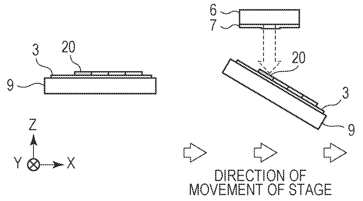
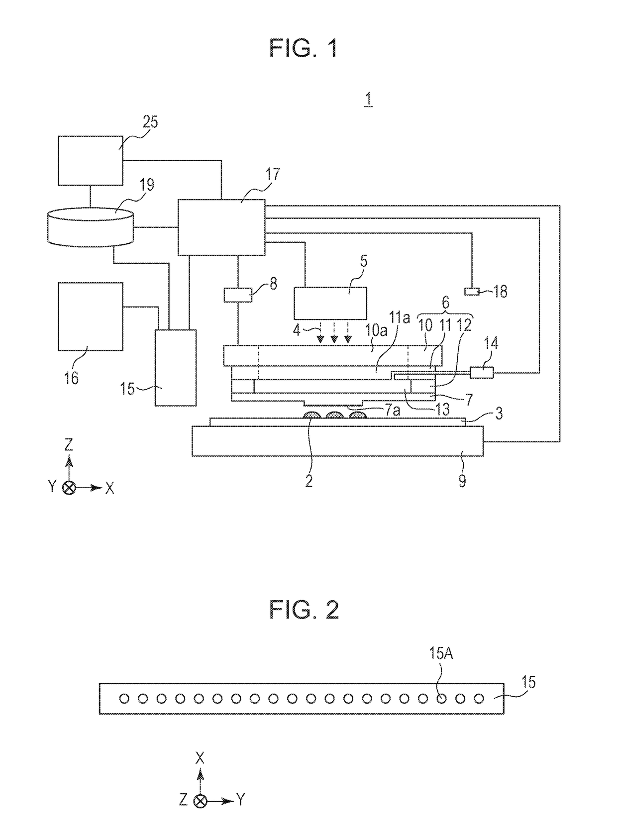
[0026]FIG. 1 illustrates an imprinting apparatus 1 according to a first embodiment of the present invention. Referring to FIG. 1, a substrate stage 9 carries a substrate 3 such as a wafer and moves along a horizontal plane. The term “horizontal plane” refers to a plane that is perpendicular to the direction of gravitational force. The phrase “to move along the horizontal plane” encompasses a case where the substrate stage 9 moves while inclining with respect to the horizontal plane by a small angle within a range of control error that may occur when the substrate stage 9 is driven. In the first embodiment, a term “information related to the state of imprint material” refers to likely nonuniformity in the thickness of a residual layer 2b (see FIGS. 6A to 6D) included in a pattern formed of imprint material that is estimated from the direction of movement of the substrate stage 9 (the information is hereinafter referred to as “likely residual-layer informat...

second embodiment

[0061]In a second embodiment of the present invention, the degree of inclination of the substrate stage 9 is acquired from the current for controlling a motor of the substrate stage 9 (hereinafter also referred to as “stage controlling current”). The stage controlling current also correlates with the direction of movement of the substrate stage 9 and the level of the force for moving the substrate stage 9. The direction of inclination of the plane at the top of the imprint material 2 according to the second embodiment corresponds to, for example, the direction of inclination of the substrate stage 9, as in the first embodiment.

[0062]FIG. 9 is a graph illustrating a relationship between the positional deviation of the substrate stage 9 and the current for controlling the substrate stage 9. The horizontal axis represents time, and the vertical axis represents the instructed position of the substrate stage 9 (the solid line), the positional deviation of the substrate stage 9 from the i...

third embodiment

[0064]In a third embodiment of the present invention, the likely residual-layer information is acquired on the basis of the direction of movement of the substrate stage 9 and information related to surface irregularities (the flatness) of the substrate 3 (irregularity information). If the substrate 3 is not flat as illustrated in FIG. 10A, the plane at the top of the imprint material 2 does not become flat, conforming to the shape of the substrate 3. Hence, the control unit 17 causes the measuring device 18 to measure surface positions of the substrate 3 with respect to the measuring device 18 and thus acquires information related to surface irregularities of the substrate 3.

[0065]FIG. 10B illustrates an exemplary control method. If the substrate stage 9 is at an angle θs with respect to the horizontal plane and a shot area 20 of interest on the substrate 3 is at an angle −θw with respect to the substrate stage 9, the mold 7 is inclined with respect to the horizontal plane by an ang...


PUM

PropertyMeasurementUnit
relative angleaaaaaaaaaa
speedaaaaaaaaaa
areaaaaaaaaaaa

Abstract

Provided is an imprinting apparatus that forms patterns sequentially on a plurality of areas of a substrate by using a mold and imprint material. The apparatus includes a moving unit configured to move along a horizontal plane while carrying the substrate, and an adjusting unit configured to adjust an inclination of the mold with respect to the substrate. The adjusting unit adjusts the inclination of the mold with respect to the substrate based on information related to a state of the imprint material provided on the substrate and information related to an order of pattern formation. The information related to the state of the imprint material on the substrate is variable with the movement of the moving unit.

Description

BACKGROUND OF THE INVENTION[0001]Field of the Invention[0002]The present invention relates to an imprinting apparatus, an imprinting method, and an article manufacturing method.[0003]Description of the Related Art[0004]An imprinting method is known as a method of forming a microscopic pattern on a substrate so as to manufacture a semiconductor device or the like. In the imprinting method, imprint material (such as light curable resin) is cast into a pattern that is formed on a substrate by using a mold having a relief pattern. If the substrate carrying the pattern is further processed in a state where a residual layer formed at the bottom of the pattern has significantly nonuniform thickness (in a state where the nonuniformity in the thickness of the residual layer is significant), a resulting article may fail to exhibit desired performance.[0005]U.S. Patent Laid-Open No. 2007 / 0228593 has disclosed a method of reducing the nonuniformity in the thickness of the residual layer. Specif...

Claims


Application Information

Patent Timeline
Patent Type & Authority Patents(United States)
IPC IPC(8): G03F9/00G03F7/00
CPCG03F7/0002G03F9/7042G03F7/201G03F7/70775H01L21/027
Inventor FUNAYOSHI, TOMOMIYAMAZAKI, TAKUROFUJIMOTO, MASAYOSHIYAMAGUCHI, HIROMITSU
Owner CANON KK
Why Eureka
Try Eureka