Compressor system for a combustion engine and combustion engine

a technology of compressor system and combustion engine, which is applied in the direction of hybrid vehicles, mechanical equipment, transportation and packaging, etc., can solve the problems of high dissipation loss and high power consumption of acceleration especially at the beginning of an operation, and achieve energy-efficient and cost-efficient operation of compressors.

Active Publication Date: 2018-04-24
FEV
View PDF25 Cites 2 Cited by
  • Summary
  • Abstract
  • Description
  • Claims
  • Application Information

AI Technical Summary

Benefits of technology

[0005]Therefore, it is a subject of the present invention to solve the aforesaid problems, at least partly. In particular, it is a subject of the invention to provide a compressor system for a combustion engine and a combustion engine, which allow an energy-efficient operation of the compressor in an especially easy and cost-efficient way, wherein simultaneously an impairment of an operation, in particular of the combustion engine, can be avoided.

Problems solved by technology

With compressors it emerged as a disadvantage that especially for mechanically actuated compressors, the acceleration especially at the beginning of an operation comprises high power consumption.
When an electrical operation is performed, a high dissipation loss can turn out disadvantageously, especially during a continuous operation.

Method used


Image

  • Compressor system for a combustion engine and combustion engine
  • Compressor system for a combustion engine and combustion engine
  • Compressor system for a combustion engine and combustion engine

Examples


Embodiment Construction

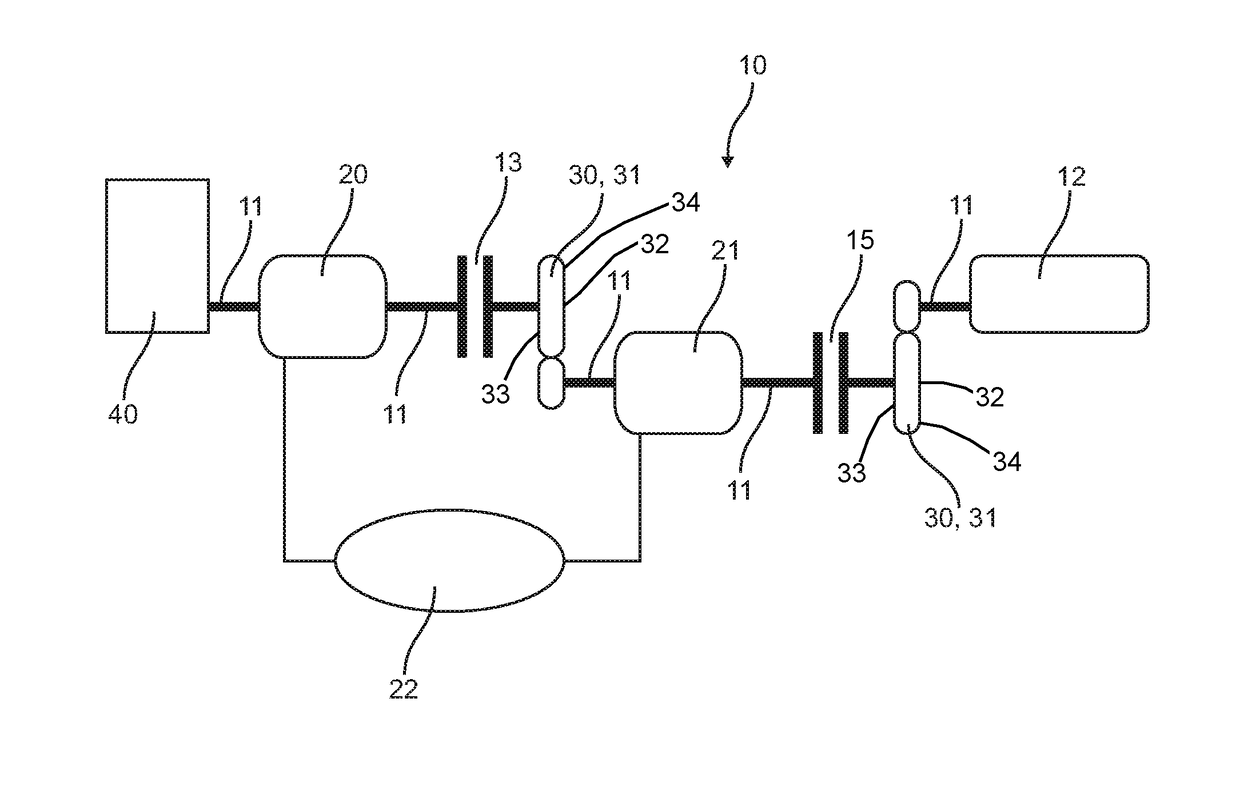
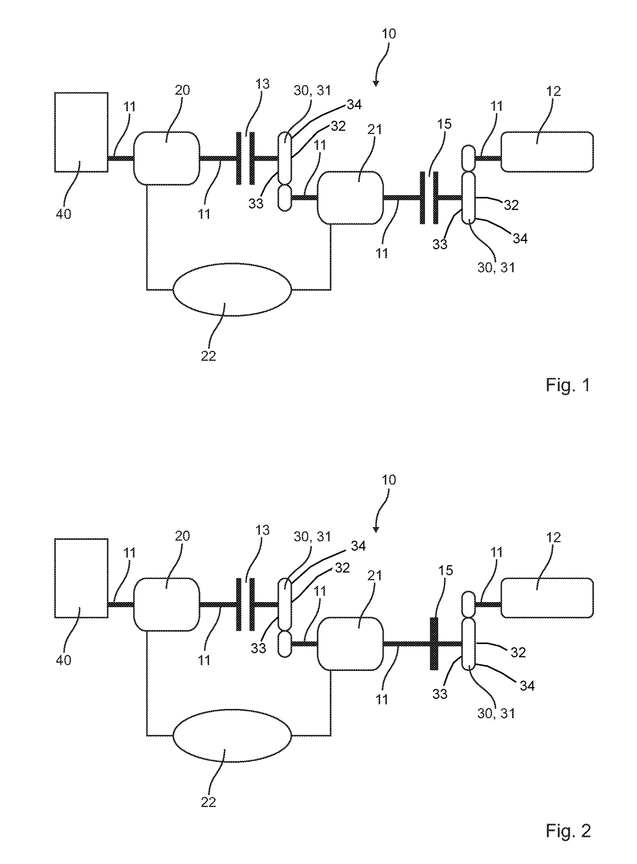
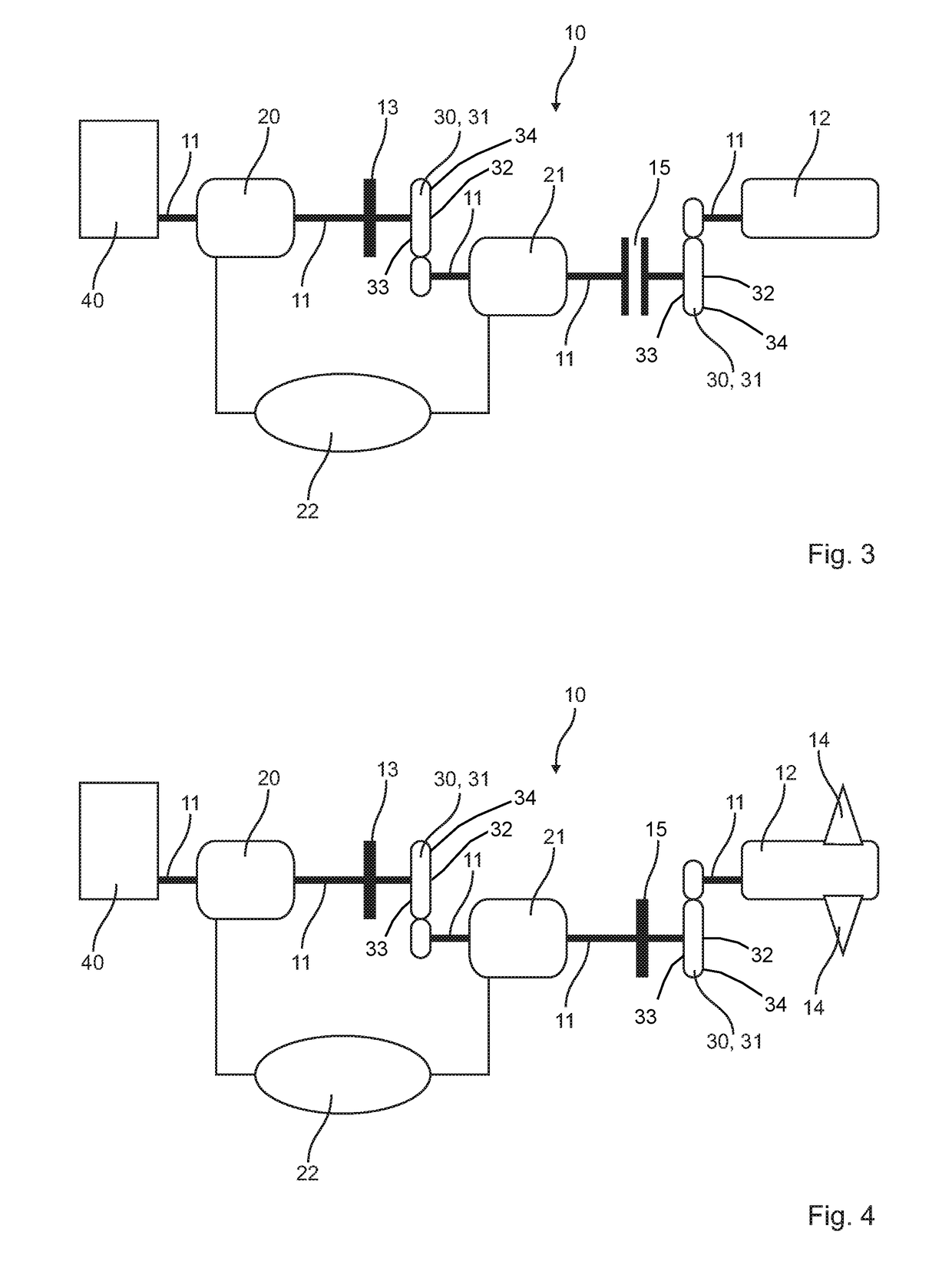
[0036]In FIGS. 1, 2, 3, 4, 5 and 6, a possible embodiment of a combustion engine 40 according to the invention with a compressor system 10 according to the invention is schematically shown. The compressor system 10 according to the invention is shown in different conditions in the separate figures. In the following, the figures are therefore described together, wherein similarities and differences of the separate conditions of the compressor system 10 according to the invention will be described in detail.

[0037]Each compressor system 10 according to the invention comprises a compressor 12, which is for instance enabled for a compression of charge air for the combustion engine 40. Further, a drive train 11 is provided, which especially enables and provides a mechanical coupling of the separate elements of the compressor system 10 to each other and in addition to the combustion engine 40. For instance, in the shown embodiment of the compressor system 10 according to the invention a fi...


PUM


Abstract

The invention is related to a compressor system (10) for a combustion engine (40), comprising a drive train (11), a compressor (12) and a first electric machine (20) mechanically coupleable by the drive train (11) with the combustion engine (40). Further the invention is related to a combustion engine (40) with a compressor system (10).

Description

CROSS-REFERENCE TO RELATED APPLICATIONS[0001]This application claims priority of German Patent Application 10 2014 118 247.2 filed Dec. 9, 2014.FIELD OF THE INVENTION[0002]The present invention is related to a compressor system for a combustion engine, comprising a drive train, a compressor and a first electric machine mechanically coupleable by the drive train with the combustion engine. Further, the invention is related to a combustion engine with a compressor system.BACKGROUND OF THE INVENTION[0003]The use of compressors at combustion engines is generally known. By use of such compressors, often as a part of a turbo charger of the combustion engine, charged air fed to the combustion engine can be compressed. A higher efficiency of the combustion engine and a lower consumption can be achieved simultaneously. In addition to an actuation via an exhaust gas turbine, as is the case with a turbo charger, alternatively or additionally, an electrical actuation of the compressor is known....

Claims


Application Information

Patent Timeline
Patent Type & Authority Patents(United States)
IPC IPC(8): F02B33/44B60K6/485F02N11/00F02B39/04F02B33/00F02B39/10F02B39/12F02B63/04F02N11/04
CPCF02B39/10B60K6/485F02B39/04F02B63/04F02N11/003F02B39/12F02N11/04F02N11/006F02B37/04Y02T10/62
Inventor SCHNORBUS, THORSTEN
Owner FEV
Why Eureka
Try Eureka