Steel work box

a work box and steel technology, applied in the field of work boxes, can solve the problems of frequent damage to expensive tools and equipment, requiring an enormous amount of time each day, and avoiding and achieving the effect of convenient movement, convenient storage, and eliminating the hassle of daily loading and unloading of tools and equipmen

Active Publication Date: 2018-05-01
ROSE KEITH E +1
View PDF20 Cites 0 Cited by
  • Summary
  • Abstract
  • Description
  • Claims
  • Application Information

AI Technical Summary

Benefits of technology

[0006]The present invention provides a heavy duty all metal welded work box that can be preloaded and conveniently stored, eliminating the hassle of loading and unloading tools and equipment daily. The work box can be easily moved from a storage container to a work location or from work location to work location, while providing protection to its contents during the convoy. The present work box saves money by increasing productivity and minimizes tool and equipment breakage. The work box not only prevents damage to tools and equipment but also preserves their longevity.
[0007]It is, therefore, an object of the present invention to provide a metal work box including a base having a horizontal planar member having an upper surface and a lower surface. The metal work box also includes a plurality of side walls secured to and extending upwardly from the base. The plurality of side walls include a front first side wall formed along a front first edge of the base, a back second side wall formed along a rear second edge of the base, a left third side wall formed along a left side third edge of the base, and right fourth side wall formed along a right side fourth edge of the base. A door is formed along the front first side wall. The door includes a door panel having a free edge and a hinged edge, the hinged edged being pivotally secured to a front hinge side wall portion of the front first side wall so as to enable easy access to contents. The front first side wall also includes a latch extending between a front latch side wall portion of the front first side wall and the free edge of the door panel to allow for selective latching of the door panel to the front latch side wall portion to keep the door securely closed.
[0008]It is also an object of the present invention to provide a metal work box wherein the upper surface of the horizontal planar member is provided with an anti-slip textured coating for safety.

Problems solved by technology

This common practice requires an enormous amount of time each day.
Also, expensive tools and equipment are frequently damaged during transfer in the insecure bucket of a front loader.

Method used


Image

  • Steel work box
  • Steel work box
  • Steel work box

Examples


Embodiment Construction

[0032]The detailed embodiment of the present invention is disclosed herein. It should be understood, however, that the disclosed embodiment is merely exemplary of the invention, which may be embodied in various forms. Therefore, the details disclosed herein are not to be interpreted as limiting, but merely as a basis for teaching one skilled in the art how to make and / or use the invention.

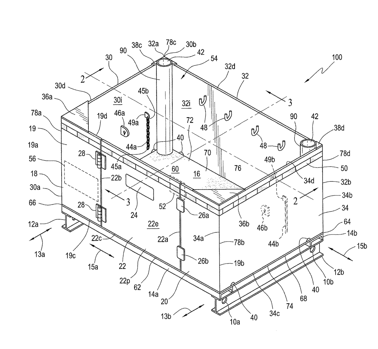
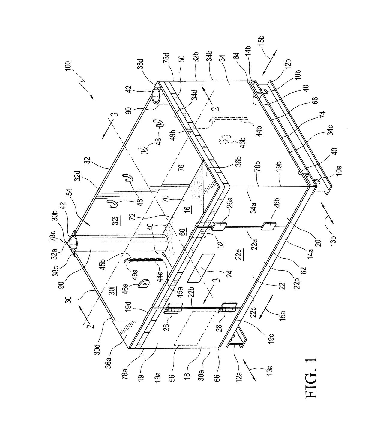
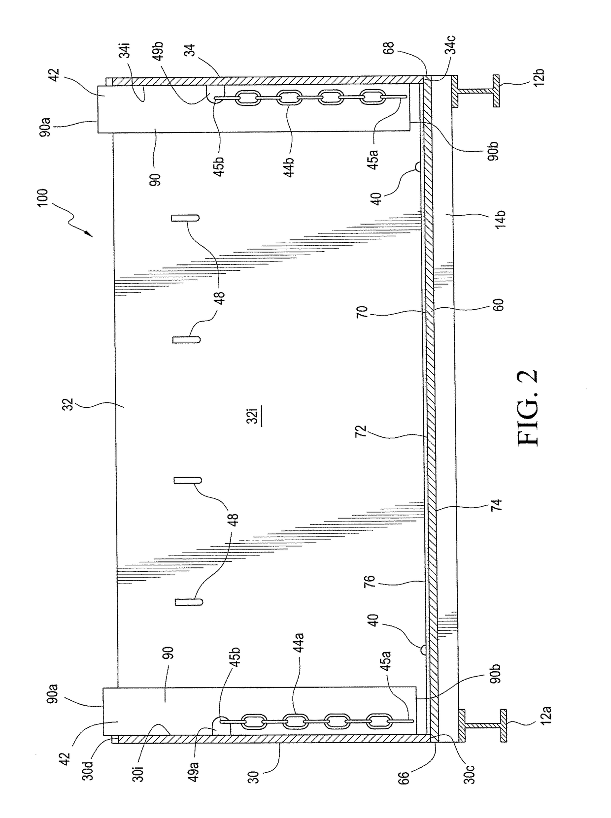
[0033]Briefly, and with reference to FIGS. 1 to 6, a steel work box 100 is disclosed. While the work box 100 is disclosed herein as being constructed from steel, it is appreciated other metals may be used so long as they provide for the strength, stability and durability required for operation of the present work box at a construction site.

[0034]Briefly, the work box 100 includes a door 22 on hinges 28 enabling easy access to the contents of the work box 100 and making adding or removing heavy objects from the work box 100 much easier. The company's logo 24 will be attached to the face of the door ...


PUM

PropertyMeasurementUnit
weightaaaaaaaaaa
stabilityaaaaaaaaaa
sizesaaaaaaaaaa

Abstract

A metal work box includes a base having a horizontal planar member having an upper surface and a lower surface. The metal work box also includes a plurality of side walls secured to and extending upwardly from the base. The plurality of side walls include a front first side wall formed along a front first edge of the base, a back second side wall formed along a rear second edge of the base, a left third side wall formed along a left side third edge of the base, and right fourth side wall formed along a right side fourth edge of the base. A door is formed along the front first side wall. The door includes a door panel having a free edge and a hinged edge, the hinged edge being pivotally secured to a front hinge side wall portion of the front first side wall so as to enable easy access to contents. The front first side wall also includes a latch extending between a front latch side wall portion of the front first side wall and the free edge of the door panel to allow for selective latching of the door panel to the front latch side wall portion to keep the door securely closed.

Description

CROSS REFERENCE TO RELATED APPLICATION[0001]This application claims the benefit of U.S. Patent Application Ser. No. 62 / 154,079, filed Apr. 28, 2015, entitled “STEEL WORK BOX.”BACKGROUND OF THE INVENTION[0002]1. Field of the Invention[0003]The invention relates to a work box for storage and transport of tools at a work site.[0004]2. Description of the Related Art[0005]On a construction site multiple employees start out their shift by unloading tools and equipment from a storage container and into the front bucket of a front loader. The tools and equipment are then moved via the front loader to the work location and unloaded. Each time the work location changes throughout the shift the tools and equipment are loaded, moved and unloaded. Finally, at the end of the shift the tools and equipment are loaded once more, transported and unloaded out of the loader bucket back into the storage container. This common practice requires an enormous amount of time each day. Also, expensive tools a...

Claims


Application Information

Patent Timeline
Patent Type & Authority Patents(United States)
IPC IPC(8): B25H3/02B65D88/10B65D90/14
CPCB25H3/02B65D90/14B65D88/10B01D50/20A47L9/1683A47L9/20B01D2279/55E01H1/0827E01H1/103
Inventor ROSE, KEITH EBOLDRIDGE, III, JOHN H
Owner ROSE KEITH E
Why Eureka
Try Eureka