Tube head with insert forming a barrier

a technology of inserts and tubes, applied in the field of flexible tubes, can solve the problems of tube head being broken down by the product, affecting the barrier properties of inserts, and unsatisfactory for certain applications, and achieve the effect of limiting the stress on inserts

Active Publication Date: 2018-05-01
ALBEA SERVICES SAS
View PDF9 Cites 1 Cited by
  • Summary
  • Abstract
  • Description
  • Claims
  • Application Information

AI Technical Summary

Benefits of technology

[0013]The invention thus makes it possible to provide a tube head comprising an insert which forms a barrier which thus protects the body of the tube head from the product which it contains, and also forms a film seal which separates the internal volume of the tube prior to its first use.
[0015]According to an aspect of the invention, said insert is arranged so as to be substantially perpendicular to a longitudinal axis of the neck. In other words, said insert is substantially planar. A feature of this type has the advantage of limiting stresses on an insert by shapes which are too sharply conical, that is to say have too narrow a point angle. Such shapes cause the insert to be worked during formation, and working of this type risks weakening said insert, particularly the metal barrier layer thereof.

Problems solved by technology

The tube head is, however, commonly produced by plastics injection, and this may prove to be unsatisfactory for certain applications owing to the very aggressive nature of some products.
However, tube head structures of this type are complex and expensive to produce, the barrier properties of the insert are diminished owing to the significant plastic deformation to which it is subjected, and the prolonged periods of storage of the product may therefore lead to the tube head being broken down by the product.

Method used


Image

  • Tube head with insert forming a barrier
  • Tube head with insert forming a barrier
  • Tube head with insert forming a barrier

Examples


Embodiment Construction

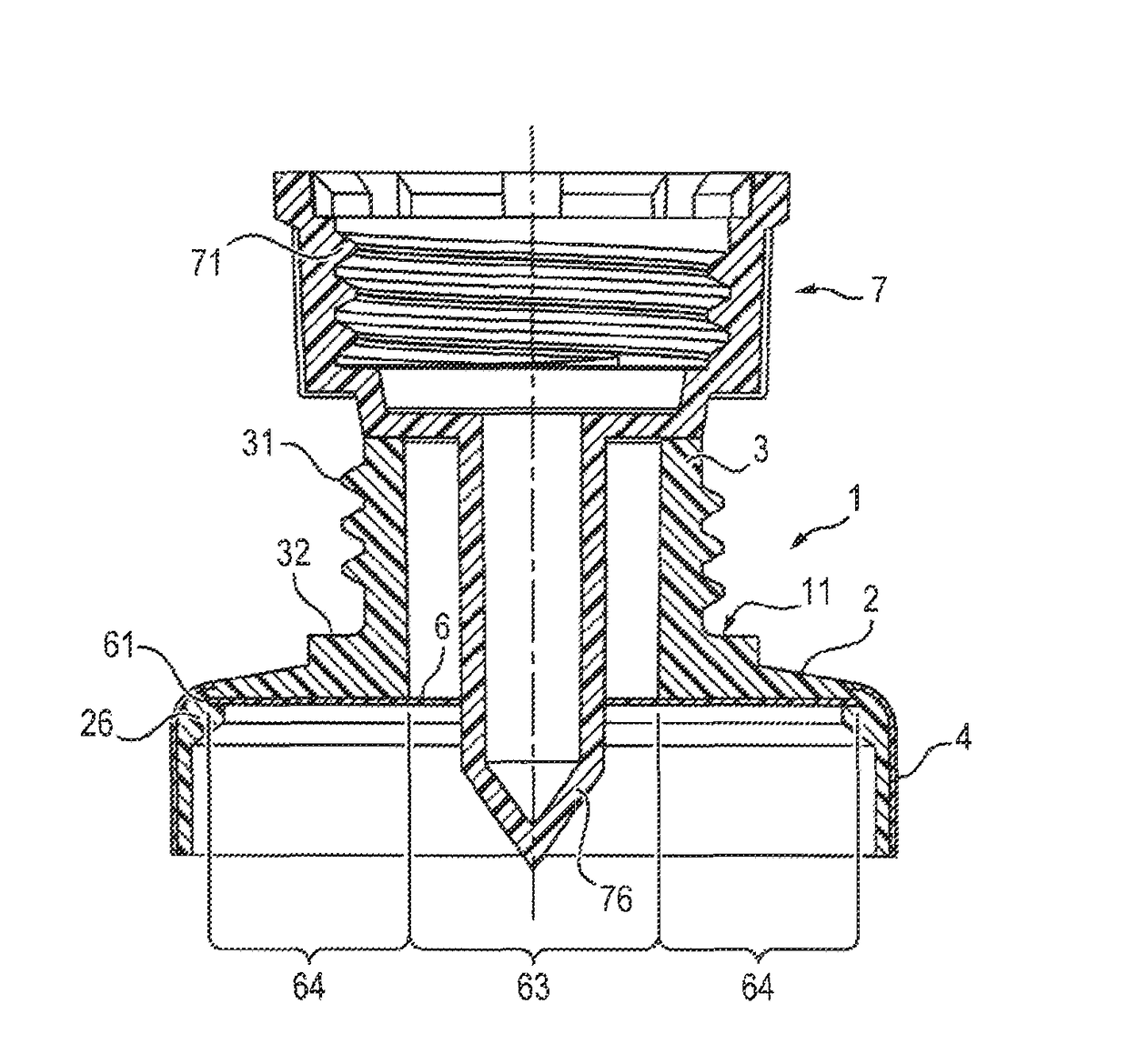
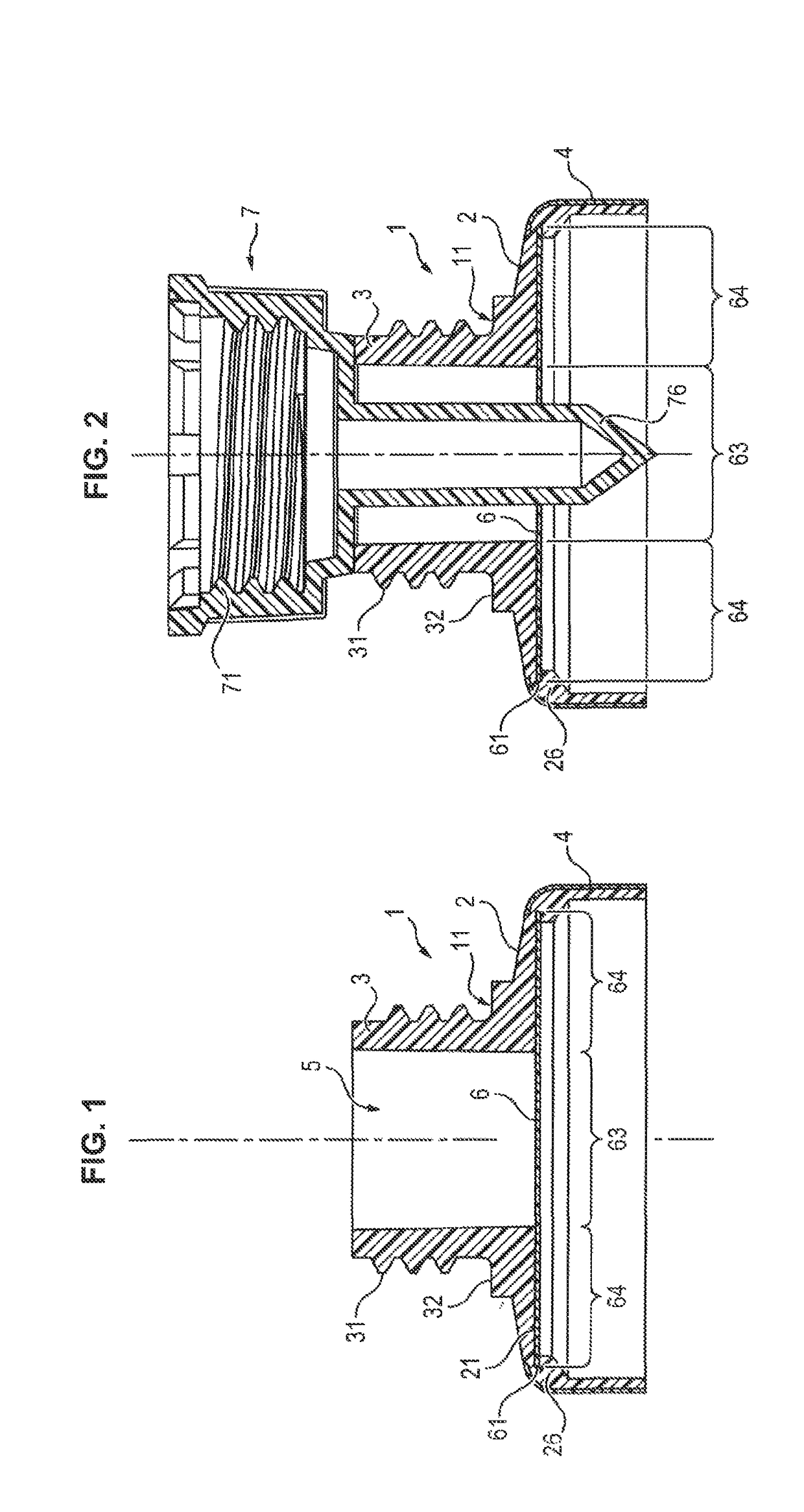
[0026]FIG. 1 is a cross-sectional view of a tube head 1 according to an aspect of the invention.

[0027]The tube head 1 comprises a body 11 comprising a shoulder 2 and a neck 3 connected to the shoulder 2.

[0028]The shoulder 2 is connected to a skirt 4 which forms the body of the associated tube and thus defines an internal volume of the tube.

[0029]The neck 3 defines an internal passage 5 which is used for distributing a product contained in the internal volume of the tube. In the embodiment shown, the neck 3 comprises an external thread 31 which makes it possible for a cap to be screwed onto said neck 3, and a bearing surface 32 which can function as a stop for a cap of this type.

[0030]The tube head 1 is connected to the skirt 4, typically by overmolding the tube head 1 on the skirt 1, or for example by welding or bonding when joining the skirt 4 to the tube head 1 formed previously, more particularly by injection molding or by compression injection molding, or by any other technique....


PUM


Abstract

A tube head is provided which is designed to be associated with a skirt so as to form an internal volume of the tube. The tube head includes a body formed from plastics material, that includes a neck having an opening at a first end, through which opening a product is removed from the internal volume of the tube, and a shoulder which is joined to a second end of the neck opposite the first end. The tube head also includes an insert arranged so as to be in contact with said shoulder and forming a barrier between the body and the product contained in the internal volume. The insert includes a central portion and a peripheral region. The central portion forms a non-perforated disc sealing the neck, and the peripheral region being mounted so as to as to be in contact with a complementary planar surface of the body.

Description

CROSS REFERENCE TO RELATED APPLICATIONS[0001]This application claims priority under 35 U.S.C. § 119(a) to French Patent Application Serial Number 1258047, filed Aug. 28, 2012, entitled “IMPROVED TUBE HEAD COMPRISING AN INSERT FORMING A BARRIER”, the entire teachings of which are incorporated herein by reference.BACKGROUND OF THE INVENTION[0002]Field of the Invention[0003]The present invention relates to the field of flexible tubes, and more specifically to the heads of such tubes.[0004]Description of the Related Art[0005]Flexible tubes commonly consist of a tube head associated with a skirt, the tube head comprising a neck for removing a product contained in the tube, while the skirt forms the internal volume of the tube which is designed to receive a product.[0006]The skirt is conventionally formed from a multi-layered sheet which is designed to have satisfactory mechanical resistance and sealing properties.[0007]The tube head is, however, commonly produced by plastics injection, a...

Claims


Application Information

Patent Timeline
Patent Type & Authority Patents(United States)
IPC IPC(8): B65D35/00B65D35/10B65D23/00B65D35/14
CPCB65D35/10B65D23/00
Inventor KERMAN, ERICMAURICE, THIERRYJAMMET, JEAN-CLAUDEHERMANT, ETIENNELIARD, JEROME
Owner ALBEA SERVICES SAS
Why Eureka
Try Eureka