Radar device, vehicle, and moving object speed detection method

a technology of radar devices and moving objects, applied in measurement devices, direction finders, instruments, etc., can solve the problems of insufficient detection precision of the relative speed of the target (or electromagnetic wave reflection parts), and the measurement error of the vehicular speed sensor tends to become larger. , to achieve the effect of improving the detection precision of the relative speed of the target and the measurement error in the traveling speed

Active Publication Date: 2018-05-01
PANASONIC CORP
View PDF23 Cites 20 Cited by
  • Summary
  • Abstract
  • Description
  • Claims
  • Application Information

AI Technical Summary

Benefits of technology

[0009]One non-limiting and exemplary embodiment provides a radar device that suppresses measurement error in traveling speed of a moving object in which the radar device is mounted (e.g., a vehicle), and improves detection precision of the relative speed of the target.
[0011]According to the present disclosure, measurement error in traveling speed of a moving object in which the radar device is mounted (e.g., a vehicle) can be suppressed, and detection precision of the relative speed of the target improved.

Problems solved by technology

The measurement error of the vehicular speed sensor tends to become larger the faster the traveling speed of the vehicle is, or the greater the acceleration is, which is problematic in that the detection precision of relative speed of a target (or electromagnetic wave reflection part) is insufficient.

Method used


Image

  • Radar device, vehicle, and moving object speed detection method
  • Radar device, vehicle, and moving object speed detection method
  • Radar device, vehicle, and moving object speed detection method

Examples


first embodiment

Modification of First Embodiment

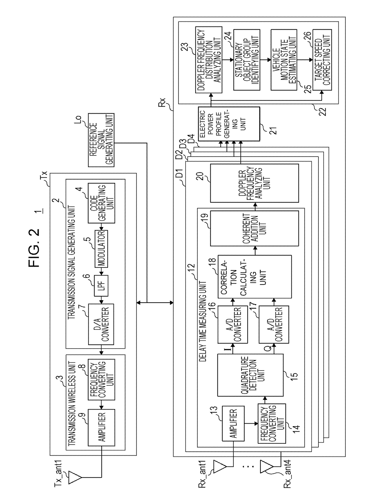
[0161]The configuration of a radar device according to a modification of the first embodiment (hereinafter referred to as “present modification”) is the same as the radar device 1 according to the first embodiment illustrated in FIG. 2, so description of the radar device 1 according to the present modification which would be redundant with the content of the radar device 1 according to the first embodiment will be simplified or omitted, and description will be made regarding content that is different.

[0162]The electric power profile Fout(k, fs, θu, w) obtained by the electric power profile generating unit 21 according to the first embodiment was three-dimensional data of discrete time k, Doppler frequency component fsΔθ, and azimuth angle θu. Accordingly, the amount of computation performed at the Doppler frequency distribution analyzing unit 23 and target speed correcting unit 26 using the electric power profile Fout(k, fs, θu, w) is great, and the m...

second embodiment

[0172]In a second embodiment, a vehicle motion state estimating unit 25A switches the vehicular speed of the vehicle CR between a vehicular speed detection value obtained from a vehicle sensor unit 31 installed in the vehicle CR and a vehicular speed estimated by the vehicle motion state estimating unit 25A (estimated value), in accordance with the detection state of the stationary object group.

[0173]FIG. 8 is a block diagram illustrating the internal configuration of a radar device 1A according to the second embodiment in detail. The configuration of the radar device 1A according to the present embodiment is a configuration where the radar device 1 according to the first embodiment illustrated in FIG. 2 further includes the vehicle sensor unit 31. Description of the radar device 1A according to the present embodiment which would be redundant with the content of the radar device 1 according to the first embodiment will be simplified or omitted, and description will be made regarding...

third embodiment

[0188]In a third embodiment, the configuration of a radar device 1B where the radar device 1A according to the second embodiment illustrated further includes a correction coefficient calculation storage unit 32, that calculates and stores correction coefficients for correcting the vehicular speed detection values obtained from the vehicle sensor unit 31, will be described with reference to FIG. 9.

[0189]FIG. 9 is a block diagram illustrating the internal configuration of the radar device 1B according to the third embodiment in detail. The configuration of the radar device 1B according to the present embodiment is a configuration where the radar device 1A according to the second embodiment illustrated in FIG. 8 further includes the correction coefficient calculation storage unit 32. Description of the radar device 1B according to the present embodiment which would be redundant with the content of the radar device 1A according to the second embodiment will be simplified or omitted, and...


PUM


Abstract

A radar device mounted in a moving object includes a radar transmitter and a radar receiver. The radar receiver includes a plurality of antenna brunch processors that perform correlation processing of the received returning signals and the radar transmission signal, and generate respective correlation signals each including arrival delay information of each of the received returning signals, an electric power profile generator that generates an electric power profiles for each arrival direction of the received returning signals and Doppler frequency component, using the generated correlation signals, and a stationary object group distribution generator that, based on the generated electric power profiles, obtains a first distribution of a Doppler frequency components of a stationary object group including a plurality of stationary objects as the plurality of targets in the perimeter of the moving object, for each azimuth angle.

Description

BACKGROUND[0001]1. Technical Field[0002]The present disclosure relates to a radar device installed in a moving object (e.g., a vehicle), the moving object in which the radar device is installed, and a moving object speed detection method of detecting a speed of travel of the moving object.[0003]2. Description of the Related Art[0004]There are known radar devices which receive returning signals reflected off of a target at an antenna array, and measure the phase difference of the reception signals received by reception antenna elements, thereby estimating a direction of arrival of returning signals from the target over a wide angle range.[0005]Examples of related art relating to installing a radar device capable of wide angle range measurement in a moving object (e.g., a vehicle), and detecting the position and relative speed of a target in the perimeter, include Japanese Unexamined Patent Application Publication No. 2004-177289 and Japanese Unexamined Patent Application Publication ...

Claims


Application Information

Patent Timeline
Patent Type & Authority Patents(United States)
IPC IPC(8): G01S13/60G01S3/46G01S13/34G01S13/26G01S7/288G01S13/93G01S13/42G01S13/931
CPCG01S13/60G01S3/46G01S7/288G01S13/931G01S13/34G01S13/42G01S13/26
Inventor KISHIGAMI, TAKAAKINISHIMURA, HIROFUMI
Owner PANASONIC CORP
Why Eureka
Try Eureka