Device for measuring blood component

a blood component and measuring device technology, applied in the direction of positive displacement liquid engine, photoelectric discharge tube, depsipeptide, etc., can solve the problems of troublesome use of fingers or hands in such diabetics, not always easy for diabetics to place, and patients may not be able to handle blood glucose meter well, etc., to achieve the effect of stabilizing operation, and reducing the number of diabetics

Active Publication Date: 2014-02-11
TERUMO KK
View PDF27 Cites 7 Cited by
  • Summary
  • Abstract
  • Description
  • Claims
  • Application Information

AI Technical Summary

Benefits of technology

[0019]The present invention has been made taking the above matters into consideration. A first object of the present invention is to provide a blood component measuring apparatus, which allows a spotted portion of a test piece to be brought into contact readily and with certainty with a blood drop obtained by puncture, thereby to suppress errors in measurement. A second object of the present invention is to provide a blood component measuring apparatus, which can carry out reading of data simply, conveniently, quickly and stably.

Problems solved by technology

Incidentally, many diabetics are elderly and sometimes use of fingers or hands in such diabetics is made troublesome due to complications from diabetes.
Further, even if able to freely use the fingers or hands, some patients may not be able to handle a blood glucose meter well due to shaking of the fingertips due to psychological factors or the like, if the patient is unaccustomed to operation of the blood glucose meter.
In particular, since a blood drop obtained by puncturing is very small, it is not always easy for a diabetic to place the spotted portion of the test piece into contact with the blood drop.
Further, if the procedure described above is carried out with trembling hands, sufficient blood may not be impregnated into the test paper, even if the spotted portion comes into contact with the blood drop.
According to research carried out by the inventor of the present application, it has been found that there are many patients whose hands are unstable if both arms are left in a free state in the air, thus making it difficult to bring the spotted portion into contact with the blood drop.
However, many patients have been found who fail, if their wrists are placed on a table, to suitably set the direction of the blood glucose meter, due to the fact that the degree of freedom in operation of the wrists is suppressed, and ultimately it is difficult to bring the spotted portion into contact with the blood drop.
Such a situation impairs visibility and sometimes makes it less easy to carry out the spotting operation.
First, since a barcode reader is provided at the distal end, there is a possibility that a laser beam emitted upon scanning may be directed toward the patient and cause the patient to experience discomfort.
Secondly, since the barcode reader and a distal end measurement portion are disposed very near to each other, there is a possibility that a test piece, which is mounted on the distal end measurement portion, may hit against some different body (including a living body) upon reading of the barcode. If such a hit occurs before measurement of the blood glucose level is taken, then there is a possibility that the spotted portion of the test piece may become soiled or broken, resulting in a measurement failure. Further, if such a hit occurs after measurement of the blood glucose level, since blood sticks onto the spotted portion, a different body with which the spotted portion comes into contact may become soiled.
Thirdly, since a monitor is disposed in proximity to the distal end measuring portion, the distal end portion has a considerable size, which impedes balance. Further, since a gripping portion is positioned rearwardly with respect to the monitor, the gripping portion is positioned far from the distal end measuring portion. As a result, the distal end measuring portion is likely to become unstable.

Method used


Image

  • Device for measuring blood component
  • Device for measuring blood component
  • Device for measuring blood component

Examples


Embodiment Construction

[0067]In the following descriptions, an embodiment of a blood component measuring instrument according to the present invention will be described with reference to FIGS. 1 to 20 of the accompanying drawings.

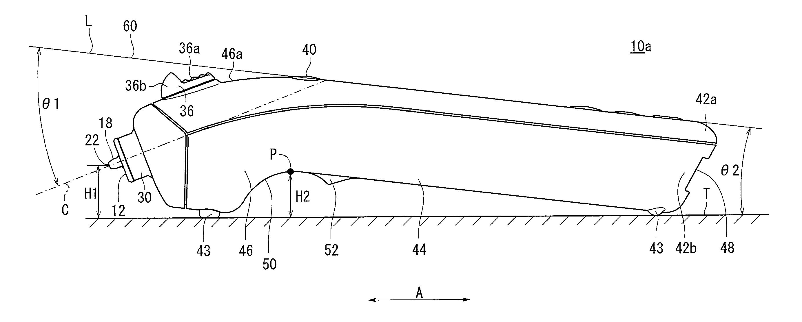
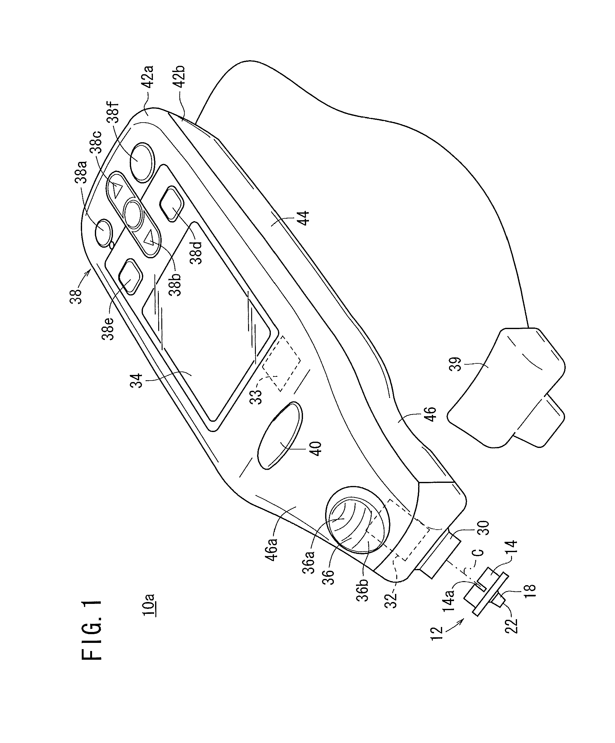
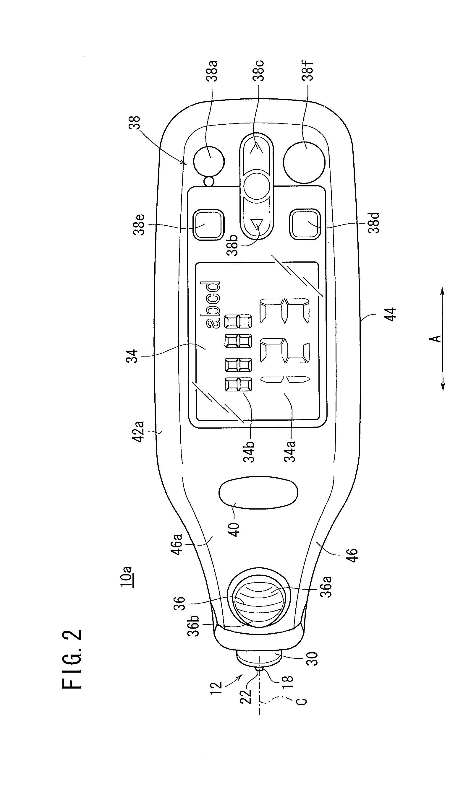
[0068]As shown in FIGS. 1, 2, 3 and 4, the blood glucose meter (blood component measuring instrument) 10a according to the present embodiment includes a distal end on which a test piece 12 is mounted. The blood glucose meter 10a has a function of storing values obtained by blood glucose measurements carried out a plural number of times. In medical facilities, the single blood glucose meter 10a can be used for blood glucose measurements of a plurality of patients. First, the test piece 12 shall be described.

[0069]As shown in FIG. 5, the test piece 12 includes a base tube 14, a flange 16 that covers one end of the base tube 14, a conical projection 18 projecting from the flange 16, and a test paper 20, which is stuck to the rear face of the flange 16. A plurality of slits 14a (refe...


PUM

PropertyMeasurementUnit
distanceaaaaaaaaaa
distanceaaaaaaaaaa
angleaaaaaaaaaa

Abstract

A blood glucose meter includes a front attachment part to which a test piece is attached, a measurement part for measuring a component of blood collected via a blood guide passage in the test piece, and a monitor for displaying the measurement results obtained by the measurement part. When the device is placed on a horizontal plane by referring to the display face of the monitor as the upper side and the opposite side as the lower side and placing the display face of the monitor upward, the central axis of the test piece extends obliquely downward toward the front side. The blood glucose meter comprises a main part provided with the monitor and a linking part between the main part and the front attachment part. The top face of the linking part is placed roughly parallel to the central axis line and is provided with an ejector lever.

Description

TECHNICAL FIELD[0001]This invention relates to a blood component measuring apparatus (device) for measuring a component such as glucose from blood sampled through a blood introduction path in a test piece, which is mounted on a distal end mounting portion of the blood component measuring apparatus.BACKGROUND ART[0002]Daily management by measurement of variations in blood glucose levels is recommended to diabetics. A blood glucose meter has been placed into practical use, in which a measurement portion, such as a test paper impregnated with a reagent that develops a color in response to the amount of glucose in blood, is provided. Blood is applied to the test paper so that the test paper develops a color, and the degree of the color is measured optically and calculated in order to display the blood glucose level (for example, refer to Japanese Utility Model Registration No. 3135393 (FIGS. 2 and 8), Japanese Laid-Open Patent Publication No. 2000-046834, and U.S. Pat. No. 7,077,328). T...

Claims


Application Information

Patent Timeline
Patent Type & Authority Patents(United States)
IPC IPC(8): G01N15/06
CPCA61B5/14546A61B2562/08A61B5/14532G01N33/48785G01N21/8483G01N21/78A61B5/1455A61B2562/0295Y10T436/11Y10T436/25375
Inventor OHASHI, HIROTAKA
Owner TERUMO KK
Why Eureka
Try Eureka