Lens apparatus and image pickup apparatus including the same

a technology of lens and pickup device, which is applied in the field of lens apparatus, can solve the problems of difficult to downsize the lens apparatus, difficult to achieve manual operation, and risk of wire breaking, and achieve the effect of easy mounting and dismounting of the driving apparatus

Active Publication Date: 2018-05-01
CANON KK
View PDF17 Cites 1 Cited by
  • Summary
  • Abstract
  • Description
  • Claims
  • Application Information

AI Technical Summary

Benefits of technology

[0009]It is therefore an object of the present invention to provide a lens apparatus, which allows a user to easily mount and dismount a driving apparatus to and from a lens, and has mounting and dismounting structure between the lens and the driving apparatus in view of impact resistance, operability, a shielding property, an static electricity resistance property, a dustproof property, and a dripproof property, and to provide an image pickup apparatus including the lens apparatus. In order to achieve the above-mentioned object, according to one embodiment of the present invention, there is provided a lens apparatus, including: a lens barrel comprising an operation ring that is rotatable about an optical axis of an optical system to operate a movable optical member included in the optical system; and a driving apparatus that engages with the operation ring to drive the operation ring in a mounted state on the lens barrel, wherein the driving apparatus includes a first communication unit and an operation unit, wherein the lens barrel includes a second communication unit, wherein a communication between the lens barrel and the driving apparatus is established through the first communication unit and the second communication unit, wherein in the mounted state, the first communication unit is disposed on a surface covering a part of an outer peripheral surface of the lens barrel, and is located on a object side with respect to an operation unit that is arranged closest to an image side in an optical axis direction of the optical system on the driving apparatus.
[0010]According to the one embodiment of the present invention, it is possible to provide the lens apparatus, which allows the user to easily mount and dismount the driving apparatus to and from the lens barrel, and can be increased in impact resistance, operability, shielding property, static electricity resistance property, dustproof property, and dripproof property, and to provide the image pickup apparatus including the lens apparatus.

Problems solved by technology

The driving apparatus is capable of driving a variety of operation of the lens in order to smoothly take a shot at a fixed angle of view or with zooming at ultra-low speed, which is difficult to achieve by manual operation.
As a result, it is difficult to downsize the lens apparatus.
However, in a case of this structure, there are a large number of processes of mounting and dismounting the driving apparatus 2, and there is a risk of breaking of a wire when disconnecting the cable 3.
Accordingly, a user cannot easily mount and dismount the driving apparatus 2.
However, in a case where the driving apparatus 7 has the above-mentioned structure, when a user drops the driving apparatus 7 in a solitary use state as illustrated in FIG. 9, the communication unit 9 is liable to locally undergo application of load, which is disadvantageous for impact resistance.

Method used


Image

  • Lens apparatus and image pickup apparatus including the same
  • Lens apparatus and image pickup apparatus including the same
  • Lens apparatus and image pickup apparatus including the same

Examples


first embodiment

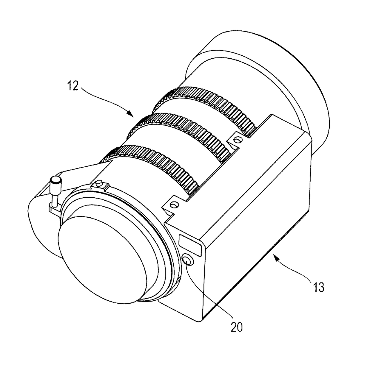
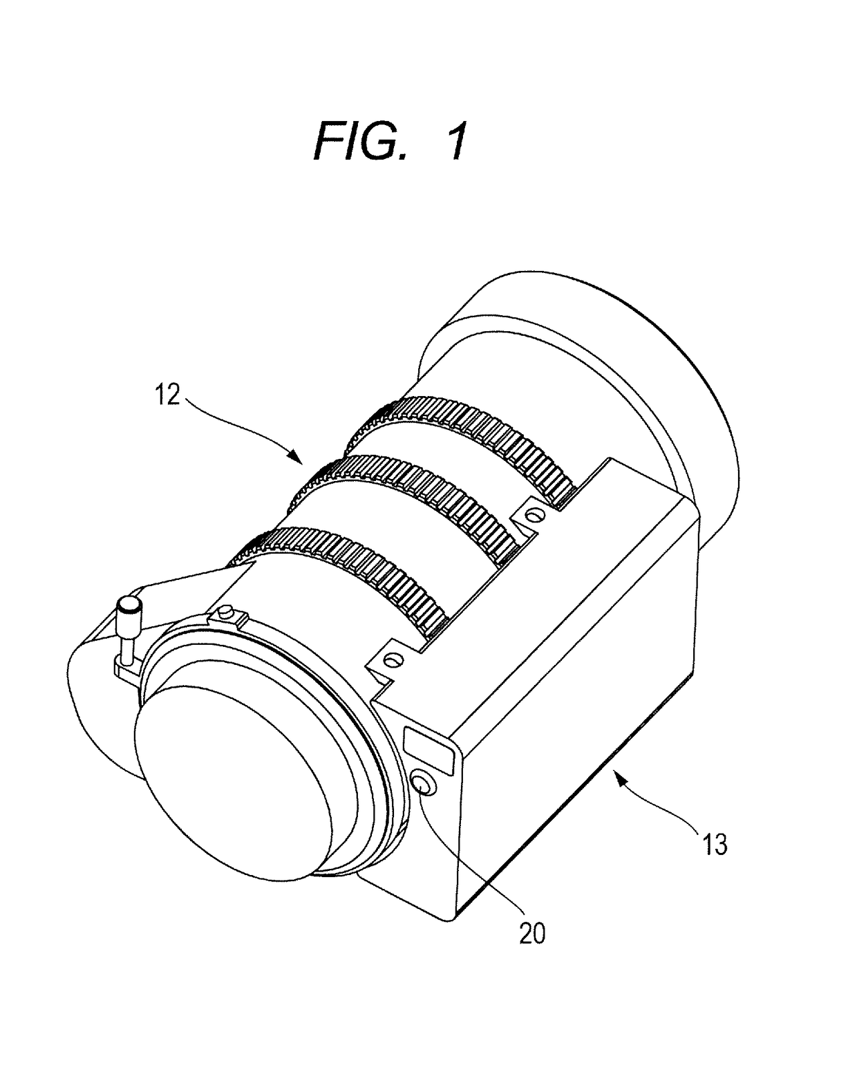
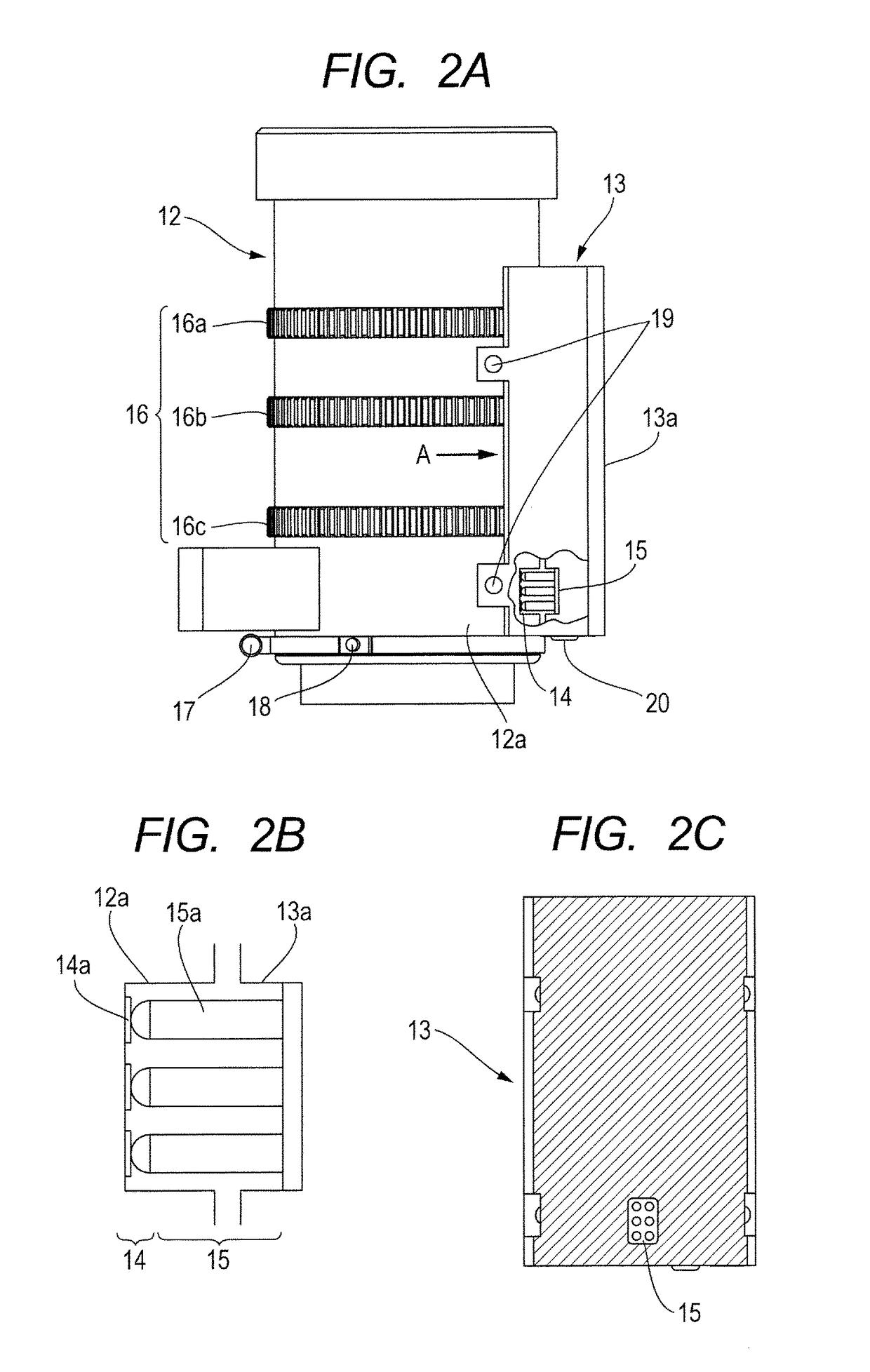
[0028]FIG. 1 is a perspective view illustrating mounting and dismounting structure between a lens and a driving apparatus of a lens apparatus according to a first embodiment of the present invention. FIGS. 2A, 2B, and 2C are detailed views illustrating the mounting and dismounting structure between the lens and the driving apparatus of the lens apparatus according to the first embodiment of the present invention. Further, FIG. 3 is a view illustrating a mounting and dismounting state of the mounting and dismounting structure between the lens and the driving apparatus of the lens apparatus according to the first embodiment of the present invention. FIGS. 4A and 4B are views illustrating a state in which the driving apparatus of the lens apparatus according to the first embodiment of the present invention is dropped, to thereby receive an impact.

[0029]With reference to FIGS. 1, 2A, 2B, and 2C, an outline of the lens apparatus is described.

[0030]The mounting and dismounting structure b...

second embodiment

[0038]FIGS. 5A and 5B are detailed views illustrating mounting and dismounting structure between a lens and a driving apparatus according to a second embodiment of the present invention. This embodiment differs from the first embodiment in that, instead of the communication units 14, 15, communication units 21, 22 (the second communication unit 21, the first communication unit 22) are used. The communication units 21, 22 have structure that employs sensors 21a, 22a having non-contact structure. The other components are the same as those of the first embodiment. In the following, only different parts from the first embodiment are described. The same components are denoted by the same reference symbols, and description thereof is omitted.

[0039]The communication units 21, 22 are described with reference to FIGS. 5A and 5B. FIG. 5B illustrates states of the communication units 21, 22 when the driving apparatus 13 is fixed to the lens barrel 12. The sensor 21a on the lens barrel 12 side ...


PUM


Abstract

Provided is a lens apparatus, including: a lens barrel comprising an operation ring rotatable about an optical axis of an optical system to operate a movable optical member included in the optical system; and a driving apparatus engaging with the operation ring to drive the operation ring in a mounted state on the lens barrel, wherein the driving apparatus includes a first communication unit and an operation unit; the lens barrel includes a second communication unit; communication between the lens barrel and driving apparatus is established through the first and second communication units; in the mounted state, the first communication unit is disposed on a surface covering a part of an outer peripheral surface of the lens barrel; and is located on a object side relative to an operation unit arranged closest to an image side in an optical axis direction of the optical system on the driving apparatus.

Description

BACKGROUND OF THE INVENTION[0001]Field of the Invention[0002]The present invention relates to a lens apparatus, and more particularly, to a lens apparatus which a driving apparatus configured to drive a lens is mountable to and dismountable from, and to an image pickup apparatus including the lens apparatus.[0003]Description of the Related Art[0004]In general, a driving apparatus is mounted to a lens configured to take moving images for professional use. The driving apparatus is capable of driving a variety of operation of the lens in order to smoothly take a shot at a fixed angle of view or with zooming at ultra-low speed, which is difficult to achieve by manual operation. However, in recent years, the lens has been used in various ways as in cinematography using the lens independently. Accordingly, there is an increasing demand for a lens driving apparatus having the structure usable in a dismountable manner as well as the structure usable in a state of being fixed to the lens. As...

Claims


Application Information

Patent Timeline
Patent Type & Authority Patents(United States)
IPC IPC(8): G03B5/00G03B3/10
CPCG03B5/00G03B3/10G03B2205/0053
Inventor TANAKA, YUHEISHIBASAKI, GOU
Owner CANON KK
Why Eureka
Try Eureka