Piezoelectric blower
a blower and piezoelectric technology, applied in the field of blowers, can solve the problems of dust clogging the inlet, the fluid flow rate cannot be obtained, and the inability to reduce so as to increase the vibration amplitude, prevent the reduction of increase the discharge pressure and discharge flow rate
- Summary
- Abstract
- Description
- Claims
- Application Information
AI Technical Summary
Benefits of technology
Problems solved by technology
Method used
Image
Examples
first embodiment
[0083]A piezoelectric blower 100 according to the present disclosure is described below.
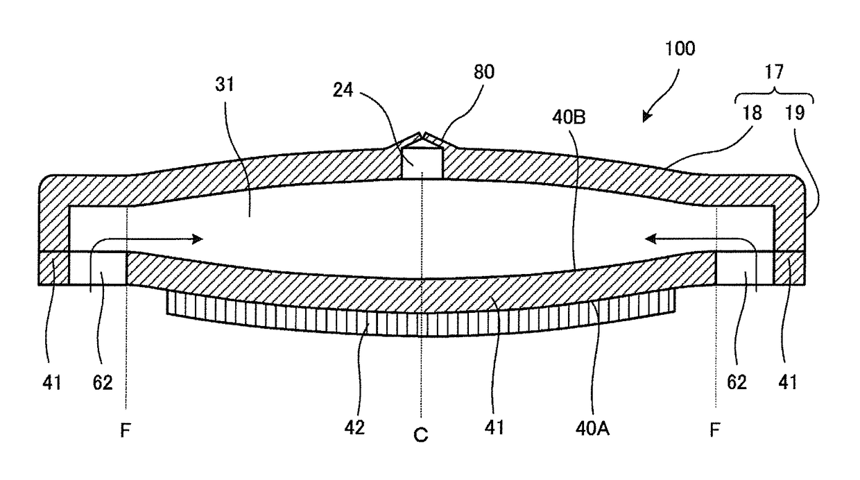
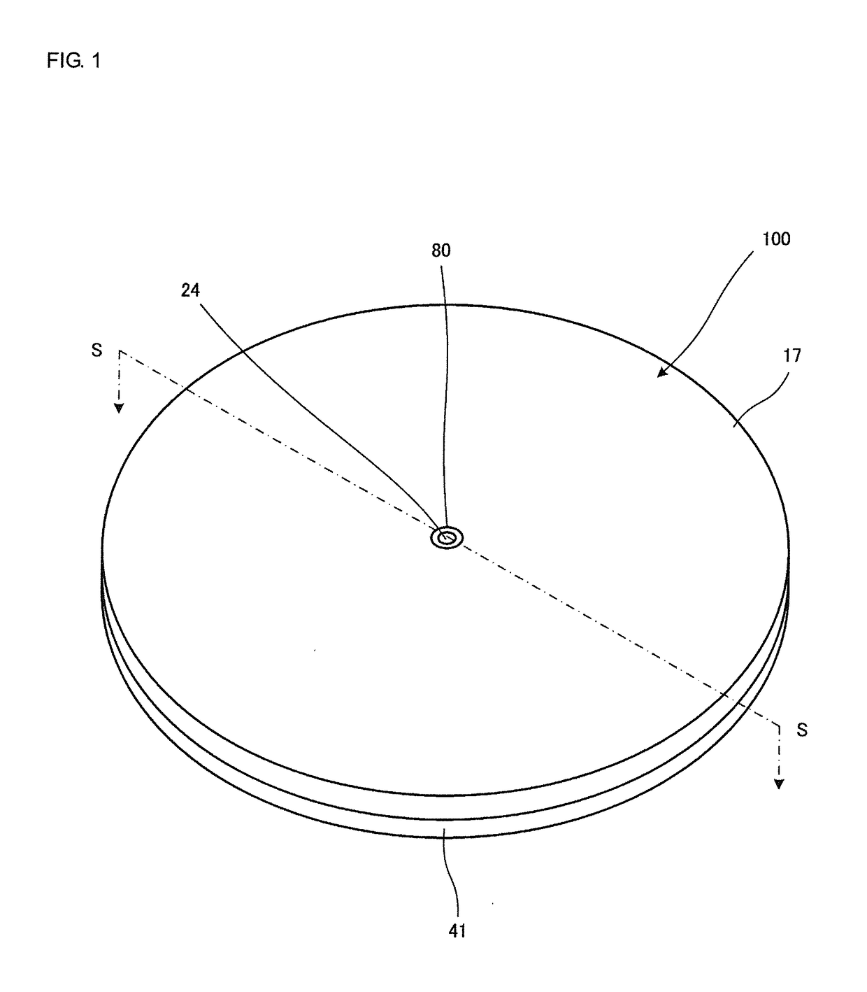
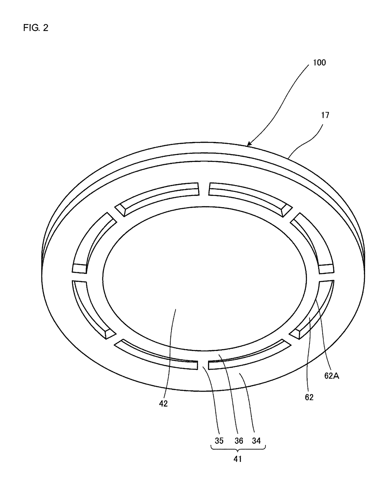
[0084]FIG. 1 is an external perspective view of the piezoelectric blower 100 according to the first embodiment of the present disclosure. FIG. 2 is an external perspective view of the piezoelectric blower 100 shown in FIG. 1. FIG. 3 is a sectional view taken along line S-S of the piezoelectric blower 100 shown in FIG. 1.
[0085]The piezoelectric blower 100 includes a valve 80, a housing 17, a vibrating plate 41, and a piezoelectric element 42 in that order from the top, and has a structure in which these components are successively placed upon each other.
[0086]In this embodiment, the piezoelectric element 42 corresponds to a “driving member” according to the present disclosure.
[0087]The vibrating plate 41 is disc-shaped, and is made of, for example, stainless steel (SUS). The thickness of the vibrating plate 41 is, for example, 0.6 mm. The diameter of a vent hole 24 is, for example, 0.6 mm. The vib...
second embodiment
[0128]A piezoelectric blower 200 according to the present disclosure is described below.
[0129]FIG. 7 is a plan view of the piezoelectric blower 200 according to the second embodiment of the present disclosure. FIG. 8 is a back view of the piezoelectric blower 200 shown in FIG. 7. FIG. 9 is a sectional view taken along line T-T of the piezoelectric blower 200 shown in FIG. 7.
[0130]The piezoelectric blower 200 includes a valve 280, a housing 217, a vibrating plate 241, and a piezoelectric element 42 in that order from the top, and has a structure in which these components are successively placed upon each other.
[0131]In this embodiment, the piezoelectric element 42 corresponds to a “driving member” according to the present disclosure.
[0132]The vibrating plate 241 is disc-shaped, and is made of, for example, stainless steel (SUS). The thickness of the vibrating plate 241 is, for example, 0.5 mm. The vibrating plate 241 includes a first principal surface 240A and a second principal surf...
third embodiment
[0176]A piezoelectric blower 300 according to the present disclosure is described below.
[0177]FIG. 13 is an external perspective view of the piezoelectric blower 300 according to the third embodiment of the present disclosure. FIG. 14 is an external perspective view of the piezoelectric blower 300 shown in FIG. 13. FIG. 15 is a sectional view taken along line U-U of the piezoelectric blower 300 shown in FIG. 13.
[0178]The piezoelectric blower 300 differs from the piezoelectric blower 100 in that the piezoelectric blower 300 does not include the valve 80 and includes a housing 317. The piezoelectric blower 300 includes a housing 17, a vibrating plate 41, a piezoelectric element 42, and the housing 317 in that order from the top, and has a structure in which these components are successively placed upon each other. Since the other structural features are the same as those of the piezoelectric blower 100, these are not described below.
[0179]The housing 317 has a C-shaped cross section h...
PUM
 Abstract
Description
Claims
Application Information
 - R&D
- Intellectual Property
- Life Sciences
- Materials
- Tech Scout
- Unparalleled Data Quality
- Higher Quality Content
- 60% Fewer Hallucinations
Browse by: Latest US Patents, China's latest patents, Technical Efficacy Thesaurus, Application Domain, Technology Topic, Popular Technical Reports.
© 2025 PatSnap. All rights reserved.Legal|Privacy policy|Modern Slavery Act Transparency Statement|Sitemap|About US| Contact US: help@patsnap.com


