Method for determining a variable of a sample

a variable and sample technology, applied in the field of methods for determining variables of samples, can solve the problems of insufficient precision, high cost, and effort implying corresponding costs, and achieve the effect of not requiring much effort in its performan

Active Publication Date: 2018-05-22
PROTECT A BOX LLC +1
View PDF18 Cites 0 Cited by
  • Summary
  • Abstract
  • Description
  • Claims
  • Application Information

AI Technical Summary

Benefits of technology

[0011]It is an object of the invention to provide a method for determining a variable of a sample in a simple way, in particular not requiring much effort in its performance.
[0027]An effect similar to the case of an excitation signal with decreasing distances between pulses can be achieved by using a frequency-modulated excitation signal the period of which decreases over time.
[0029]In the method according to the invention the sensor used is exposed to an excitation energy significantly lower than for example in phase-modulation methods of prior art. From this a reduced photo-bleaching of the sensor results, i.e. the deterioration of the sensor substance used in the sensor, i.e. of a luminescence dye, by the light used for exciting the luminescence is reduced.
[0031]The required contact, already mentioned above, between the sample and the at least one sensor substance can be achieved in a simple manner by mixing the sensor substance with the sample.

Problems solved by technology

A difficulty with these methods, however, is to implement the defined time intervals for the integration of the luminescence response with sufficient precision in the measurement apparatus.
This involves a certain technical effort implying corresponding costs.
Furthermore the technology used is very sensitive, which makes its use, in particular for portable devices in the field, problematic, in particular again with respect to costs.

Method used


Image

  • Method for determining a variable of a sample
  • Method for determining a variable of a sample
  • Method for determining a variable of a sample

Examples


Embodiment Construction

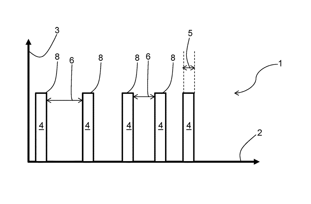
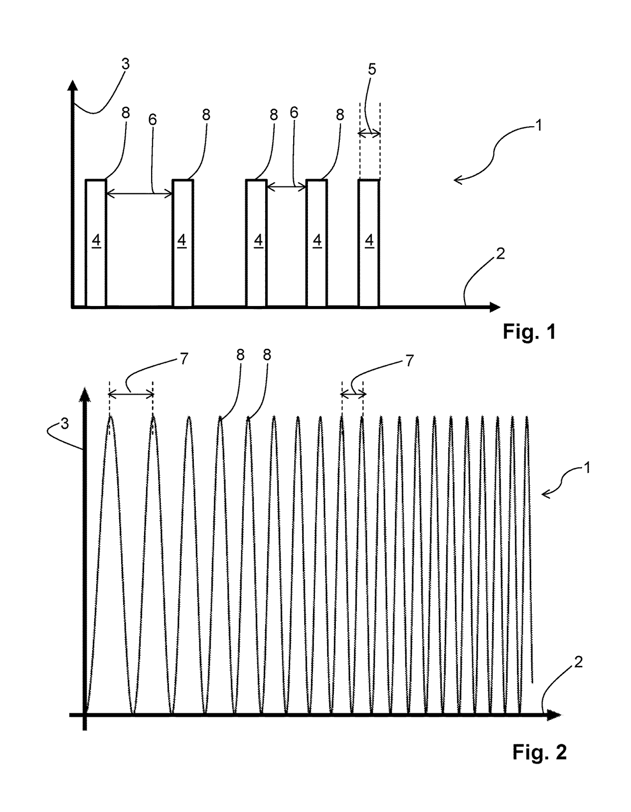
[0054]FIG. 1 shows an excitation signal 1, which is a sequence of pulses, as may be used for exciting a luminescence of a sensor substance in the method according to the invention. Time is shown on the abscissa 2, the ordinate 3 shows a measure for the strength of the excitation signal 1, for example the intensity of the excitation signal 1. The excitation signal 1 comprises a sequence of pulses 4, and is characterized by pulse durations 5 and distances 6 between pulses. In the sequence of pulses shown, the pulse durations 5 are constant over the duration of the sequence of pulses, the distances 6 between pulses, however, decrease from pulse 4 to pulse 4. The sum of pulse duration 5 and distance 6 between pulses for the rectangular pulses shown here corresponds to the temporal distance of consecutive signal maxima 8. The decreasing distances 6 between pulses therefore imply that the distances between consecutive signal maxima 8 of the excitation signal 1 decrease over the duration o...


PUM

PropertyMeasurementUnit
luminescence behavioraaaaaaaaaa
relaxation timeaaaaaaaaaa
temporal distanceaaaaaaaaaa

Abstract

A method for determining a variable of a sample is provided. At least one sensor substance is brought into contact with the sample and excited to luminesce by means of an electromagnetic excitation signal. The sensor substance is such that a relaxation time of its luminescence behavior depends on the variable of the sample to be determined. The electromagnetic excitation signal has a defined time-dependence, it is, for example, a frequency-modulated signal or a pulse sequence, in which distances between pulses are varied over the duration of the excitation signal. The time dependence of the luminescence response of the sensor substance is detected and an output signal is generated therefrom by integrating over specified time-intervals. An instant of time, relative to the time-dependence of the excitation signal, is determined, at which a step occurs in the time-dependence of the output signal. The value of the variable is determined from said instant of time. A preceding calibration can be advantageously used for this purpose.

Description

[0001]This is a Continuation of International Patent Application No. PCT / IB2014 / 063765, filed Aug. 7, 2014 which claims the benefit of German Patent Application DE 10 2013 109 010.9, filed Aug. 21, 2013, both of which are hereby incorporated by reference herein.[0002]The present invention relates to a method for determining a variable of a sample, more specifically to a method in which the variable of the sample is determined from the luminescence behavior of a sensor substance.BACKGROUND[0003]The German published patent application DE 196 34 873 A1 describes an apparatus and a method for discriminating, by a time-resolved fluorescence measurement, at least two differently fluorescing types of molecule groups bound to analyte molecules. Therein a light source for illuminating a sample volume is activated for a time-interval T1, then, after a time-interval T2, a detector is activated for a time T3. Which of the at least two molecule groups are contained in the sample volume is determ...

Claims


Application Information

Patent Timeline
Patent Type & Authority Patents(United States)
IPC IPC(8): G01N21/64G01K11/20
CPCG01K11/20G01N21/6408
Inventor LIEBSCH, GREGORANDRZEJEWSKI, DAMIAN
Owner PROTECT A BOX LLC
Why Eureka
Try Eureka