Universal phone battery chargers for mobile cellphones and like devices

a universal phone and charger technology, applied in the field of universal phone chargers, can solve the problems of short shelf life of telephone chargers, unfavorable or comfortable use, and the availability of battery packs in various configurations, and achieve the effect of convenient holding

Active Publication Date: 2018-05-22
SORIASKY YEOSHUA
View PDF17 Cites 13 Cited by
  • Summary
  • Abstract
  • Description
  • Claims
  • Application Information

AI Technical Summary

Benefits of technology

[0006]Accordingly, it is an object of the present invention to provide a very slim, standardized, rectangularly shaped battery body that is very flat and thin and can be easily held against the back of a cellphone, carried in a shirt pocket, or even in a man's wallet and usable with virtually all mobile phones on the market.
[0011]The charging accessory has an on / off switch and a charging level display configured to indicate a charge level of the internal battery and preferably first and second charging plugs for enabling selective charging of different type mobile devices. The first and second charging plug have a curved outer surface which matches a curved outer shape of the body of the charging accessory, so the battery / charger overall assembly has a smooth rectangular shape. Preferably, the plug-in accessory comprises charger contacts located in grooves formed in the plugin accessory to help to assist in preventing human contacts with said charger contacts.

Problems solved by technology

Among the drawbacks of the prior art, including the charger prior art described in the aforementioned patents, arises from the fact that the prior art chargers are provided in a packaging that doubles as a telephone case for the cellphone, whereby the telephone is installed into and integrated with the telephone chargers.
In actuality, this results in very short shelf life telephone chargers, owing to the very rapid and constant changing of telephone designs.
Another drawback of the prior art is that battery packs are provided in various configuration, usually as rectangular and lengthy “stick” shaped objects that are not conducive or comfortable to hold in a man's pocket or shirt pocket.
Another drawback of the prior art chargers is associated with the fact that they typically require dangling cables with connectors on opposed ends that are required to be utilized between the telephone chargers or the battery pack and the mobile phone itself, leading to inconvenience or tangled wires and similar drawbacks.

Method used


Image

  • Universal phone battery chargers for mobile cellphones and like devices
  • Universal phone battery chargers for mobile cellphones and like devices
  • Universal phone battery chargers for mobile cellphones and like devices

Examples


Embodiment Construction

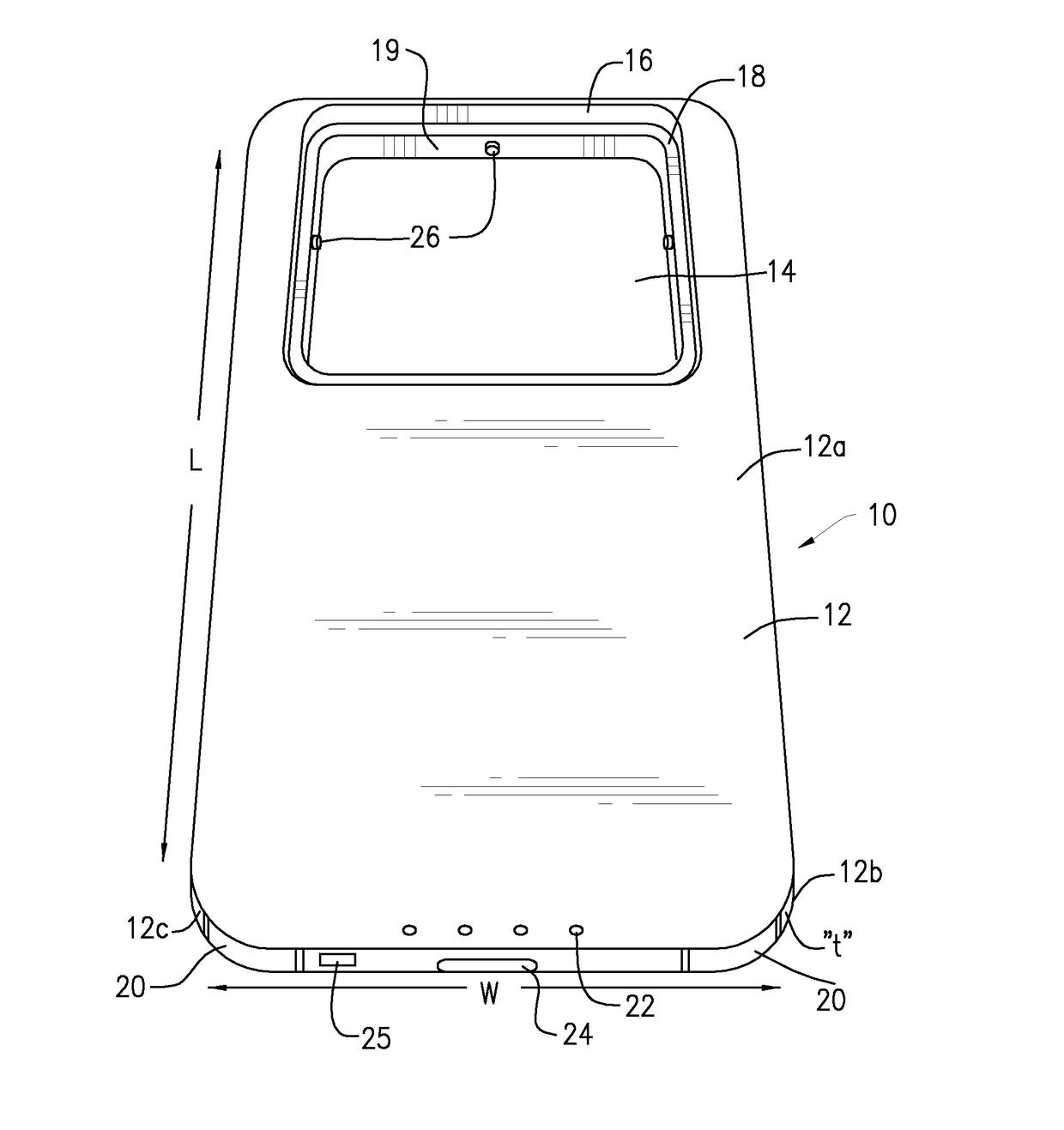
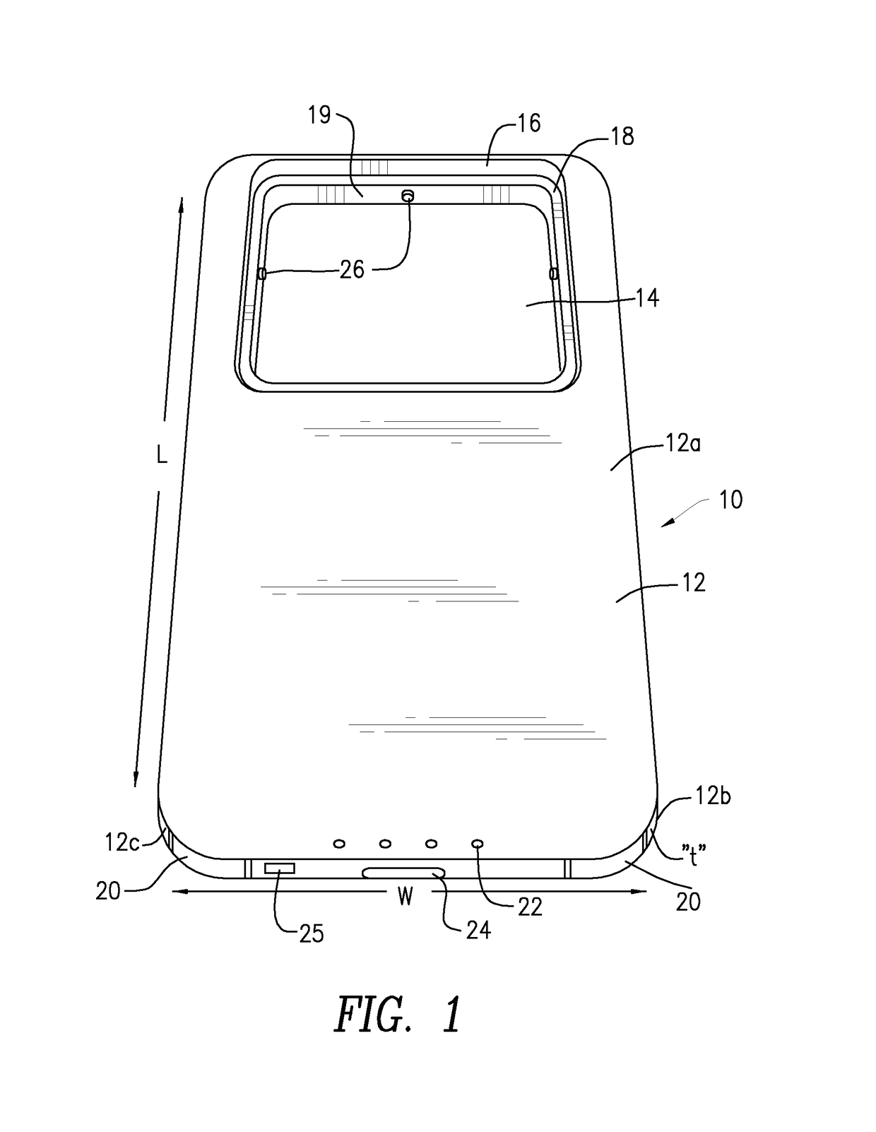
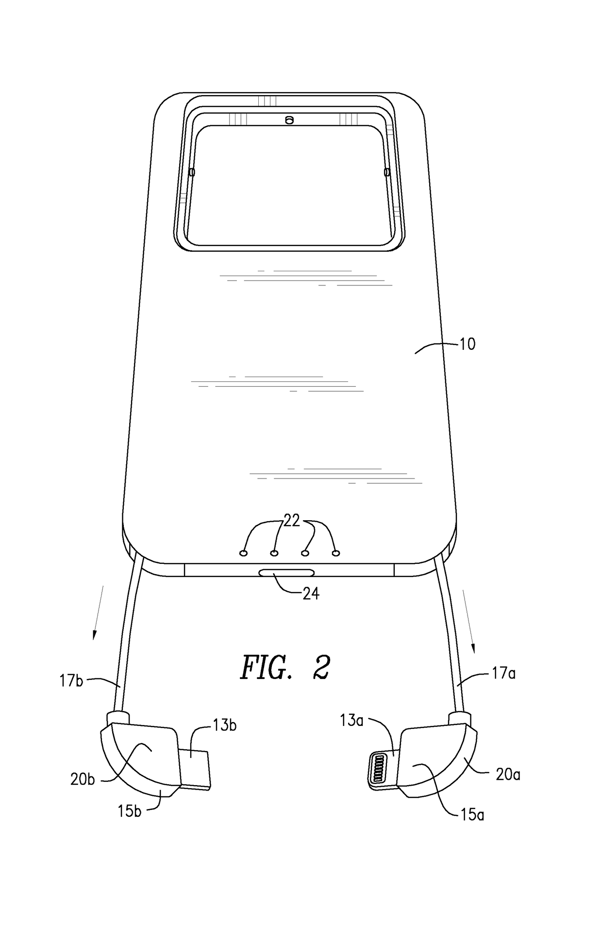
[0034]Referring to the drawings, for quicker grasping of the overall concept of the present invention, initial reference is made to FIG. 7 which shows a conventional cellphone 1, for example an iPhone, lying front face down and having attached to the rear surface thereof a battery pack or module 10 that incorporates a removable charger module 30 with pivotal AC prongs 36. The battery module 10 has a normally concealed charging cable 17a and an accompanying telephone compatible charging plug 20a which is selectively attachable to the cellphone 1 to charge its internal battery. The shape, dimensions and thickness of the battery module 10 allows it to be palm-held while using the telephone, as the thickness thereof is substantially the same as a typical cellphone, on the order of less than 10 mm and preferably between 5 to 7 mm. The battery module 10 is illustrated more fully in FIG. 1 and one example of its removable charger is illustrated in FIG. 3a.

[0035]Referring to FIG. 1, the ba...


PUM


Abstract

A universal charging accessory for mobile devices. The accessory has a generally flat and thin body configured to lie flat against the flat rear side of the mobile device and includes an internal rechargeable battery, two charging plugs that are configured to be electronically coupled to the charging plug of the mobile device, with the charging plugs being retrievably stowed inside the body of the accessory and to be withdrawn as needed to charge the mobile device. The accessory has a window formed in the body of the charging accessory which receives, interchangeably, a plug-in module that can be inserted into an AC socket to charge the internal battery as well as the cellphone battery.

Description

CROSS-REFERENCE TO RELATED APPLICATION[0001]This application claims the benefit and priority of U.S. Provisional patent application Ser. No. 62 / 385,419, filed Sep. 9, 2016 entitled UNIVERSAL PHONE CASE STYLE BATTERY CHARGER FOR MOBILE CELL PHONES AND LIKE DEVICES, the entire disclosure of which is incorporated herein by reference.BACKGROUND OF THE INVENTION[0002]The present invention is generally directed to battery chargers, optionally with an included auxiliary battery and, more particularly, to universal battery chargers for cellphones and like mobile devices that can be utilized with many different cellphone devices and which can be used with future mobile phones, substantially without regard to future cellphone configurations.[0003]The general background and technology for the present invention is described in the present inventor's issued U.S. Pat. Nos. 9,413,179 and 9,088,670, the entire contents of which are incorporated by reference herein. The background art is also descri...

Claims


Application Information

Patent Timeline
Patent Type & Authority Patents(United States)
IPC IPC(8): G06F1/16H02J7/00H02J7/02H04M1/02
CPCG06F1/1632H02J7/0044H04M1/0274H02J7/02H02J7/0045H04M1/185G06F1/263H02J7/342H02J7/0048H02J7/00
Inventor SORIAS, YEOSHUAMOSKOWITZ, MAX
Owner SORIASKY YEOSHUA
Why Eureka
Try Eureka